_2d2230.png)
_5a42ce.png)

GalaxyGuy
Manuf/Distrib/Whole
-
Joined
-
Last visited
Everything posted by GalaxyGuy
-
Try the new beta version. It supports multiple accounts on Android. The released iOS version already has the capability. https://www.sm-alarms.co.uk/apps/main/getAVKPAPP.php The SelfMon VKP works on all models. It also works with anything that supports a secure IP tunnel. WebWay Etc. One caveat is the G2 series, where the LCE module is needed to provide the virtualkeypad, as Honeywell's module doesn't provide it.
-
Let me correct some assumptions in your questions. I'll also try to give an unbiased view, but will note that I run SelfMon Ltd, so will let others chime in if they feel I am being misleading in any way. Firstly, the Flex V3 does not accept the E080 modules. It will only offer full IP functionality with the A083 Ethernet module. Honeywell reduced the cost of the A083 to ~£100, so that makes cost a bit more palatable when adding IP to the V3 panel. The LCE modules are not compatible with the V3 Flex at the moment. Both the SelfMon platform and Honeywell's push notification service work with the A083 module in the Flex V3 panel. Here's some key points and +/- of the systems: - Honeywell's notification is push notification via their GX app only, but it's free, so worth trying out to see if it suits. SelfMon supports Push, Email, SMS, Voice, URL calling and allows events to be filtered to recipients in a number of ways. It costs a minimum of £1 a month, but can cost more if you want to have multiple chargeable SMS or Voice calls above the £1 monthly limit. Support will be provided for customers with a SelfMon account. - Honeywell added an option into the Flex firmware to enable suppression of IP based issues, so if a message doesn't send, the issue is only logged to the engineering log. This allows the ARC side to take care of missing signals and makes dealing with issues much easier. This isn't available for the other Galaxy Dimension/G2/Classic panels, but an additional override was added to the LCE module to enable this for those panels. - Honeywell's push notification is free, but there is no support and it's difficult to resolve any issues with their support team. It's been reliable in general, but the mistake Honeywell made was to introduce sequential account numbers, meaning that it would be easy for a hacker to send events to all customer accounts. - SelfMon supports line path checking and the Flex V3 panel can provide a test signal at one minute granularity. To reduce load, the platform will only alert after 1hr of missing test signal. Honeywell's push notification doesn't have any missing signal check. - SelfMon supports its own DNS, making it easy for the app to call back to the premises where a dynamic IP address is being used. If you use Honeywell's GX app and have a dynamic IP address, you need a separate DNS service to reach the premises. - Neither Honeywell or SelfMon offer a graded service with any response guarantee. These systems are unmanned notification services. If police response is required, then a graded platform should be used (something dual path with decent polling of 60 minutes or less would be advisable). Can you really pick up the E080-4 or E080-8 for £70. That's pretty low considering they are normally ~£200.
-
Yes, the Dimension replaced the G3-X when the G3-X was discontinued Sept 2008. Physically, just extra trigger outputs and a bigger flash chip to hold the Dimension firmware going forward. The Dimension firmware was updated to enable RF portal connection with panel based RF configuration (unlike the old RF RIO), but adding this option lowers the installation grading to 2. The Dimension, along with Flex panels also support the touch screen Touchcenter keypads now available in a better flush-mount housing (TouchCenter+ version). The Dimension and Flex panels also integrate access control. The Dimension range is available in 48, 96, 264, 520 zones and the old G3 was 48,144,520 zones. There are a few other small differences. One key thing to note with Honeywell is that the EOL products are unlikely to receive any firmware updates/fixes.
-
Many installers will swap the board only, leaving the original PSU and case, as it's too much hassle changing the chassis. I suppose if you're lucky they will have changed the lid over to the new one, but selling what looks like a new dimension on eBay fetches more than an old g3 . Firmware version is guaranteed to give the correct type.
-
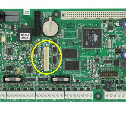
I used to think the easiest way to determine the Dimension was by the vertical trigger header, but some of the later G3 were built with this PCB just to confuse things. It's best to identify by firmware version Dimension: V6.XX or V7.XX G3: V5.XX
-
Yes, only Dimension, Flex and G2 panels have the newer interface. The 3-X panels use the same galaxy gold program as the old classic panels. The dimension is different hardware with a bigger flash chip, so there's no upgrade path for the old hardware other than switching the PCB out.
-
I thought you used this for some sites?
-
I've just had a mail from Pyronix saying that Vodafone TAP is to switch OFF March 31st. Ie. end of the month. I think this only leaves the 50p per dial option for those still using TAP based notifications.
-
OP - It sounds very much like your router does not support NAT Loopback. NAT Loopback allows connection to your own external WAN IP address from inside your private network. Check your router documentation to see if there's a setting. Other than that, you will need to switch addresses depending on which network you're on. Take a look at my Honeywell VKP app manual, as it explains this on the second last page. I don't know if Texecom mention this anywhere, but it's a very common issue. https://www.sm-alarms.co.uk/manuals/selfmon_iosvkp_v2.pdf
-
Needs to be multi-site. So at least two separate systems in different buildings - preferably different areas with different power/network infrastructure. The systems also need maintenance to ensure they are patched and have no issues.
-
Are you saying that zone 1002 is ok, or that you swapped the zones over ? The values are out of range. Ie. 836 Ohms is too low. Moisture in the cabling / sensor, wrong resistors, additional resistors Etc ? You need to fault find the reason for 836 ohms on a 1k/2k circuit. When the detector is activated, it's opening the contact bringing the circuit into the 900 to 1200 ohms range and not 2k. Are you sure the detector doesn't have integral resistors and you're adding more in parallel ? Zone closed needs to be between 900 to 1.2k ohms (best 1k). Open between 1.3k and 3.5k ohm (best 2k).
-
What's the resistance with respect to 0v on the zone wire with the zone wire removed from the panel screw terminal? With the zone wire removed from the terminal does it show any voltage (DC or AC) on the wire when measured against 0v? Next step is to swap zones and see if the problem remains or follows the wired devices. If it remains, replace the PCB. If it follows the wiring, then further investigation of the sensors and wiring is required. The Dimension firmware was changed at some point to only log marginal low/high res to the engineer log, so not surprising that these are not being reported to the arc.
-
No problem. The radio features of the Galaxy are poorly documented. I don't think I've seen it written anywhere what the fob led sequences actually mean. Perhaps I should put together a one pager.
-
If the heartbeat isn't present, it doesn't matter. The important parts are the ports and message protocol. Set to UDP outgoing port 10002 and Microtech protocol.
-
Which options are you missing? SelfMon also works on the older G3 panels with firmware before the Dimension was even born, so it should be working with your panel. Just let me know what's missing and I will advise.
-
Resistances with respect to ground and each other can be measured with power off. Anything sub 600 Ohms needs further investigation. You can look at RS485 data with a scope to ensure that the lines aren't stuck, but makes more sense if you look at the TTL output of one of the RS485 transceiver chips. The resistances may be something for on-site work and the scope for the bench.
-
Not sure if that's true about the firmware version, but would need to load old firmware to validate. Its normally the module firmware version that's the issue and not the panel. Honeywell's support is basically a database these days! Try the SelfMon.co.uk and virtualkeypad app. They're likely to work and if they don't, I'll be able to tell you exactly what's going wrong as I wrote all the underlying code.
-
As above. Also check diagnostics menu 61 and ensure comm's remain at 100%. If wiring and voltage is okay, then replace the RIO.
-
Thinking back to this post while looking at the RF portal on the Flex+ 50 V3.39 today. If you have a TCC8 fob, then pressing the lightbulb icon button will night set the Flex.
-
Only TCP port 10001 needs opened if you've opted to open a port. Other ports are outgoing. What do you mean by 'nothing happens' ? No push message from the app?
-
You need to connect to your home network by VPN or port forward. Port forward is easier to set up, but not advisable as a secure solution. If your broadband account does not offer a static IP address, you will need to use a dynamic DNS provider to resolve your WAN IP address in order to connect back to your home router.
-
All the Honeywell wireless products are designed in France. The documentation and support is dreadful.
-
The Flex was brought in as a reduced cost option for domestic / small business market. It includes Dimension firmware features, but is limited as far as number of zones/busses go. Plastic case allowing for internal RF module. Also supports click-in module mounting and energy efficient switched mode PSU that can be hard wired or plugged in to a wall socket. Range now includes Flex+ supporting Grade 3. At boot time, the Flex+ panel gives Grade 2/3 choice. Metal cased Flex also introduced - presumably as a replacement for the G2 which will eventually end-of-life. Wouldn't touch the le-sucre range.
-
No, there's no wireless option for the Galaxy range. Best to hard wire it anyway.
-
You never mentioned a tamper on 1001, so unless that zone is not being used, then no resistor required there. You aren't shorting the zones, you're just setting the zone permanently closed by placing 1k across the zone to ground (0v). Zones that are 1k are closed. Zones at 2k are open. On the G2, any higher or lower resistances are tamper. The resistance boundaries are in the manual. Here's the zones info for your G2: On the left block (RIO 0) zones are: 1001 1002 1003 1004 On the right hand block (RIO1) zones are: 1011 1012 1013 1014 - Resistor to 0v 1015 - Resistor to 0v 1016 - Resistor to 0v 1017 - Resistor to 0v 1018 - Resistor to 0v