All Activity
- Today
-
Seems GJD bought them in 2017 probably sacked everyone after that and lost all old data but you never know they might have some info for you
-
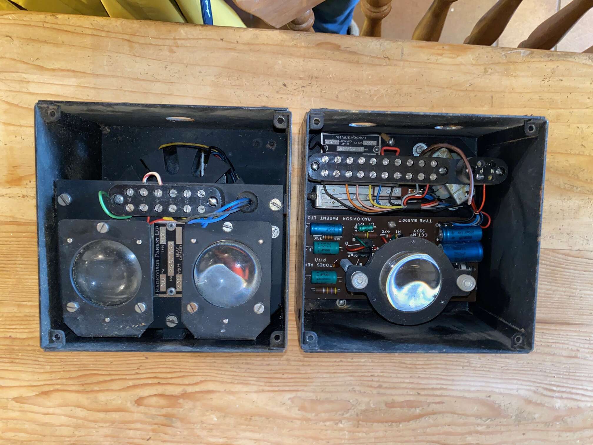
The PCB material makes me think 70s. The capacitors maybe look more modern? It's probably hard to date if they would have been hand built and low batch numbers?
-
The first production of an Led was 1962
-
You looking in mirror on a good day?
-
Mr Happy, what makes you think it might be 1970’s, is it the wiring colours or the style of the components?
-
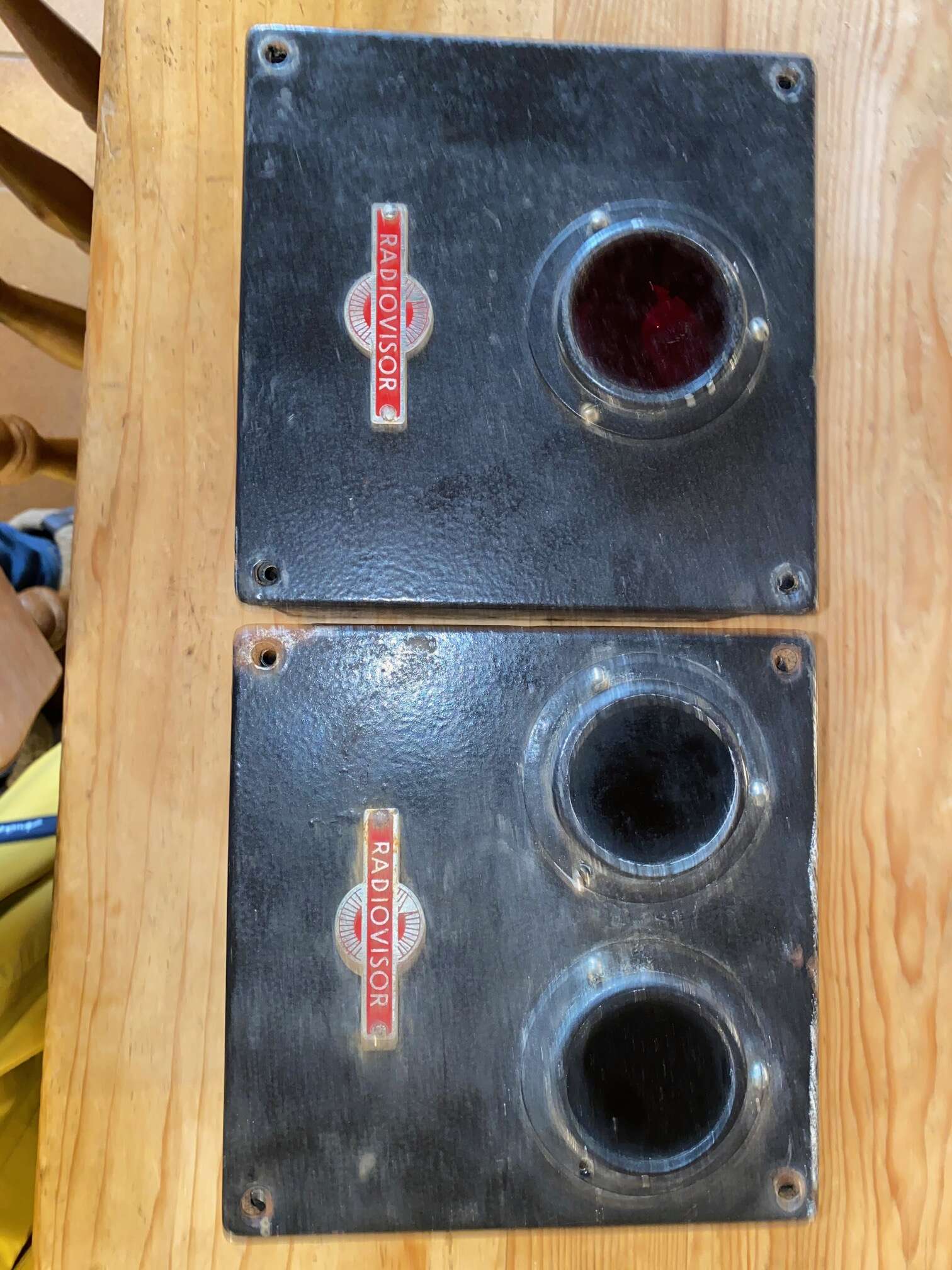
Thanks guys, those are helpful comments and confirm my thoughts although it’s useful to hear how they might have been used. When cleaning them yesterday I noticed that the single lense was red but the twin lenses are black, similar to welding goggles. I presume that the red would be the transmitter as there is a diode behind the internal curved lense?
- Yesterday
-
Looks 1970s to me ?
-
Radiovisor specialised in Active IR beams. Never seen any so old tho. They work as a pair. Usually an IR beam is emitted then reflected back it detects if something blocks this.
-
The would normally go across a large doorway or similar the modern version would look like below

-
They look like early IR beams transmitter and receiver.
-
Hi All, I’m new here and a fraud as I don’t install security alarms but came across your forum when searching Radiovisor. I’ve just picked up from a house clearance sale two intriguing wall mounted Radiovisor devices that seem to use infrared and I wanted to try and find out their original application. I will try and attach pictures but they are both around 6” square and 4” deep, one having a single lens and one having twin lenses. They are badged “Radiovisor” and inside have the type BA500T. They appear to be from the 1930-40 era but bear no dates. Can anyone give me any clues as to where they would have been used and what for as I’m intrigued by them? They’re going on the wall in the utility room, come what may, but I’d like to find out about them if I possibly can! Thanks for any help you can give! Paul King, Kent
-
 PaulKing joined the community
 -

Eaton KEY-KPZ01 rapid red flashing
al-yeti replied to AutomationEng's topic in Control Panels (Public)
Althought have you managed to delete the keypad? And need to add it back as a device Does the app allow a virtual keypad? Go through it and see if it sees keypad or not as a wired device -
Eaton KEY-KPZ01 rapid red flashing
al-yeti replied to AutomationEng's topic in Control Panels (Public)
Maybe then keypad issue -

Eaton KEY-KPZ01 rapid red flashing
james.wilson replied to AutomationEng's topic in Control Panels (Public)
Agreed sounds like a keypad comms issue. However I'd thought you would get faults reported / logged -
 nihadyong02 joined the community
 - Last week
-
Eaton KEY-KPZ01 rapid red flashing
al-yeti replied to AutomationEng's topic in Control Panels (Public)
Cable fault, I assume it worked on the bench with short cable or check there's no strand shorting out where you connect wires, if spare cores try them instead to keypad -
I programmed an i-onG2SM, in my office. PIRs door contacts, KEY-KPZ01 and network access. Everything worked OK. II then connected it to the actual system, replacing an old Ademco Galaxy. The only thing I didn't connect was the bell box. I also only had the keypad on a short wire, local to the box, while I tested everything else for a few days. This also worked. I have now connected the bell/ strobe and used the old wires to replace the Galaxy keypad with my KEY-KPZ01. For some reason the keypad will only constantly display the Eaton logo and an old date, and the navigation button rapidly flashes red. Pressing any key just causes a beep but does nothing else. The system still works through the Secureconnect app. but I can't do anything with the keypad. Any ideas would be much appreciated. Thanks in advance
-
 gerry1422 joined the community
 -

Card types and how to get the head around?
Cieska replied to Cieska's topic in General Security & Fire Queries
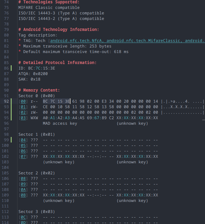
I was told that I could read the number simply when reading the card. So I guess it is not encrypted. Otherwise, I won't be fighting here. The dashes in Sectors 1 and 2 are because I would think I read this card with mobile NFC? or should I consider something not good here? Well, I'm first time using this mobile app to read the card. -

Using an old PM360 ADT Alarm System
PeterJames replied to Juan Pablo's topic in !!..DIY Installers..!!
Good old Github -
I assumed spam, but looks like good info
-
Using an old PM360 ADT Alarm System
james.wilson replied to Juan Pablo's topic in !!..DIY Installers..!!
I need to review links but I'm away from a desktop. -
I'm kind of late to the party, but the final answer to the OP question came in just a few days ago. Between heating and eating I chose... to cancel ADT subscription. At the time of the separation, ADT didn't offer any codes. Fully functional Visonic PowerMaster 360 professionally installed system became abandoned as a result primarily because of the inability to check it via the app remotely. Many thanks to Visonic Powermax and Powermaster Integration for Home Assistant OSS project, it is possible to give Visonic PowerMaster 360 a second lease of life without paying for a rather expensive and totally useless subscription. As a byproduct, the following secret codes, not shared by ADT otherwise, can be extracted from Visonic Power Master 360 and a few other panels on the list: User Codes Master Code Installer Code Master Download Code Installer Download Code Raspberry Pi Zero (£12.59 inc. VAT and shipping) will do the one off code dumping job. It will require a quality micro USB cable, a phone charger with micro USB output and an ability to follow unwritten instructions. NB Raspberry PI Zero doesn't have any network connectivity, so it will be useless for anything else. Although I have some positive experience of running Home Assistant on a sister SBC with 512 MB RAM and Wi-Fi (Zero 2W), Home Assistant hardware requirements are hugely and unreasonably inflated when it comes to RAM. Well, the internet if full of opinions and alternative facts. The panel is self contained. No cloud is required for it to operate. By plugging Home Assistant via Visonic Powermax and Powermaster Integration into PowerLink subsystem via a micro USB connector at the back, the panel is getting an ability for integration with Apple HomeKit, or any other home automation controller either natively when supported, or via MQTT. In addition, the GSM module inside the panel can be configured to send alerts via text messages. Apparently this will require a SIM on a paid contract. As a reminder, the GSM module is 2G/3G, and 3G will not exist in the UK beyond next year (with exception for so much lobbied smart meters, of course) and 2G will be switched off by 2033 at the latest.
-
 王 維 joined the community
 -

Card types and how to get the head around?
sixwheeledbeast replied to Cieska's topic in General Security & Fire Queries
I suppose these are using proprietary Crypto1 format? If so maybe look at the documentation from the people that RE'd it? -
Card types and how to get the head around?
Cieska replied to Cieska's topic in General Security & Fire Queries
Hi, I know it's my old topic, but I have come back to it. The complication is to understand Card formats and how to read the data. At the moment for example: I have a Mifare Classic 4K card the ACS system by default reads the first 32bit which is the Card Serial Numer (CSN) The system is CEMsys AC2000 I know that I need to read different numbers, which are 8-digit number encoded in Sector-1 Block-2. To read CSN in the card definition setting field of the AC2000 Start position - 1 My question is why is this not start from position - 0 ? As computers read from zero first? As otherwise then all pern doesn't match when counting bits? Or I'm wrong here? Field length - 32 this is where I match my understanding against the CSN as I can read and match the first 32bits (4bytes) or hex value, in the screenshot line 92 of my text editor where I have selected the value. So, if the block length is 128bit (per line), then my interesting data starts at the 6th line which is per block number [05] (text editor line 100) as it starts counting blocks from [00] in the sector [00]. This should mean that it should start read my interesting data from 641bit and the Field length should be 24bits (as 8 digit number fits in 3bytes https://www.rapidtables.com/convert/number/decimal-to-hex.html ) another question here is - if the 8-digit number is encoded in hex or it's just the same number but in numbers only? In other words to say, how the read data is interpreted? Or if the reader reads the CSN number and displays hext then my number also, should be displayed as simple as this? We are talking about reading unencrypted data, as I was told I should read this dara simply when scanning the card. So I have many unknowns in my head, which is why it is totally confusing. I need some guidance or tips. or anything. The
-
 bramvdh1 joined the community
 - Earlier
-

Texecom Premier Elite - tamper alarm only when door contact is closed
ywu replied to ywu's topic in !!..DIY Installers..!!
I think that's resolved it. I've got an airgap of about an inch between sensor and magnet and it's enough for the alarm to say it's "secure" that the door is "closed". -
Texecom Premier Elite - tamper alarm only when door contact is closed
ywu replied to ywu's topic in !!..DIY Installers..!!
There was a gap of around 0.75 cm between the sensor and the magnet before. Maybe i'm putting them too close together and they need that air gap? I've now tried multiple orientations and it still triggers.


-
Who's Online 1 Member, 0 Anonymous, 47 Guests (See full list)
-
Member Statistics
51,699
Total Members1,664
Most Online
-
Forum Statistics
33.2k
Total Topics443.8k
Total Posts