


_2d2230.png)
_5a42ce.png)
Jack b
-
Joined
-
Last visited
Posts posted by Jack b
-
-
-
Acquired this recently; thought I'd do a post for anyone interested.
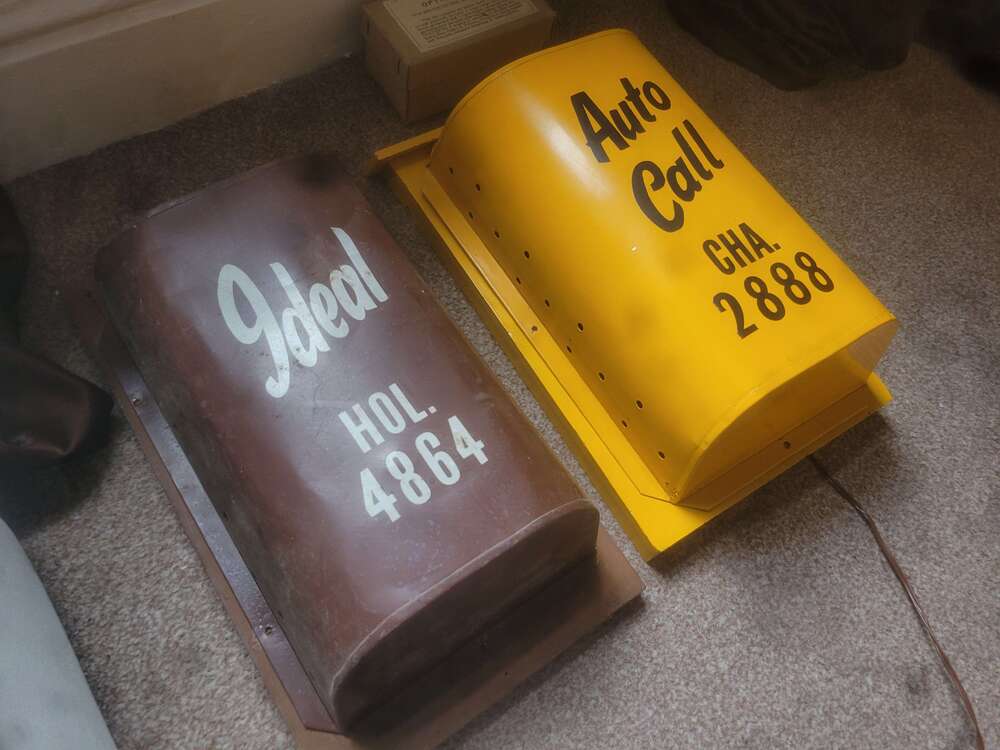
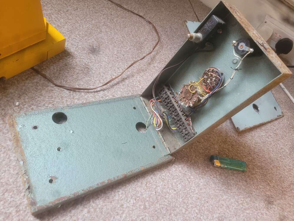
This is a very old Auto Call alarm system dating back to 1959. The control panel is what's known as a G Type. Designed by a guy called Ted Gant hence the name of the panel. Fitted by Auto Call and also Ideal Fire and Burglary.
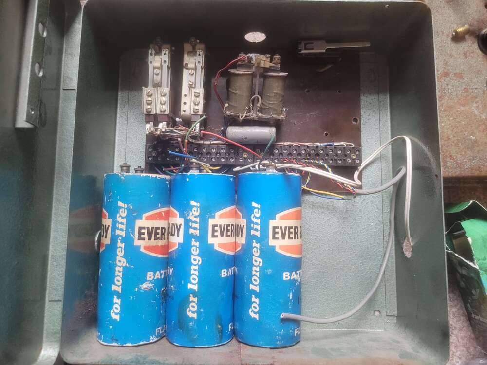
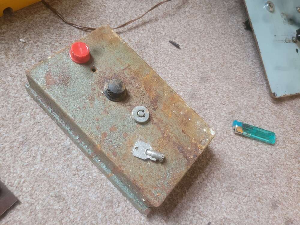
The system consists of a large panel box that houses 4 flag cell batteries and a set of control relays. Then theres a smaller hinged box known as the control panel thats got a red lamp, three position wafer switch, and keyswitch mounted to the front. Then theres the bell box which housed a gent bell and occasionally had a tamper loop around the cover. And finally a small wooden box which contained a set of flag cells connected at the end of the alarm zone/circuit.
Some systems had an auto dialler fitted top which would send a pre recorded message to a police via a vinyl record.
-
 1
1
-
-
Definitely a bit late to the party.... if there ever was one
Your SAB module is incredibly simple. It looks like it's got a very simple charging circuit in the form of a diode traced in series with a resistor used to limit the current in order to charge the nickel cadmium battery correctly. If i remember, that nicad has a 280mA capacity so youd need roughly around 10% of the capacity of the battery in current to charge it. So you'd need to calculate a resistor that can limit the current to 28mA. This will provide a trickle charge
That relay is simply just switching the battery to the bell when de energised, and it's N/O contacts is energising the charging circuit.
The tamper switch contacts are simply wired from the negative hold off to the tamper return terminal. Then the N/C side is bridging between the negative hold off and the negative of the bell. I'm assuming this is for a 24hr tamper In the form of locally sounding the bell.
-
On 21/02/2023 at 21:37, Ianfrost said:
Hello I use to work for Maxim Alarms
and use to install these systems they use to have a six volt battery in that bell cover
and a piece of plastic capping coming down the wall to a toke lock in a box where
we’re you would set they alarm
Any recollection on the SCB module inside the maxim alarm box's? I was told ages ago that it was a small transistor module fitted underneath the alarm bell?
-
On 30/05/2024 at 12:00, sixwheeledbeast said:
These detectors will be probably from the 1960s, the circuit board is made out of phenolic which was obsolete by the late 1960s with most circuit boards being made from a fiberglass material. not to mention the strowger 600 type relay being used. Also those bakelite terminals.
-
Hi, bit of a long shot as these panels are very old and most are probably skipped; but does anyone still have a modern automatic alarms traffic light panel? And are willing to sell it?
It's a hammered silver panel with a sidleen barrel key switch and its distinctive red, yellow and green lamps fitted to the top of the unit.
-
Edited by Jack b
2 hours ago, MrHappy said:ta, quite modern looking for the 60's ?
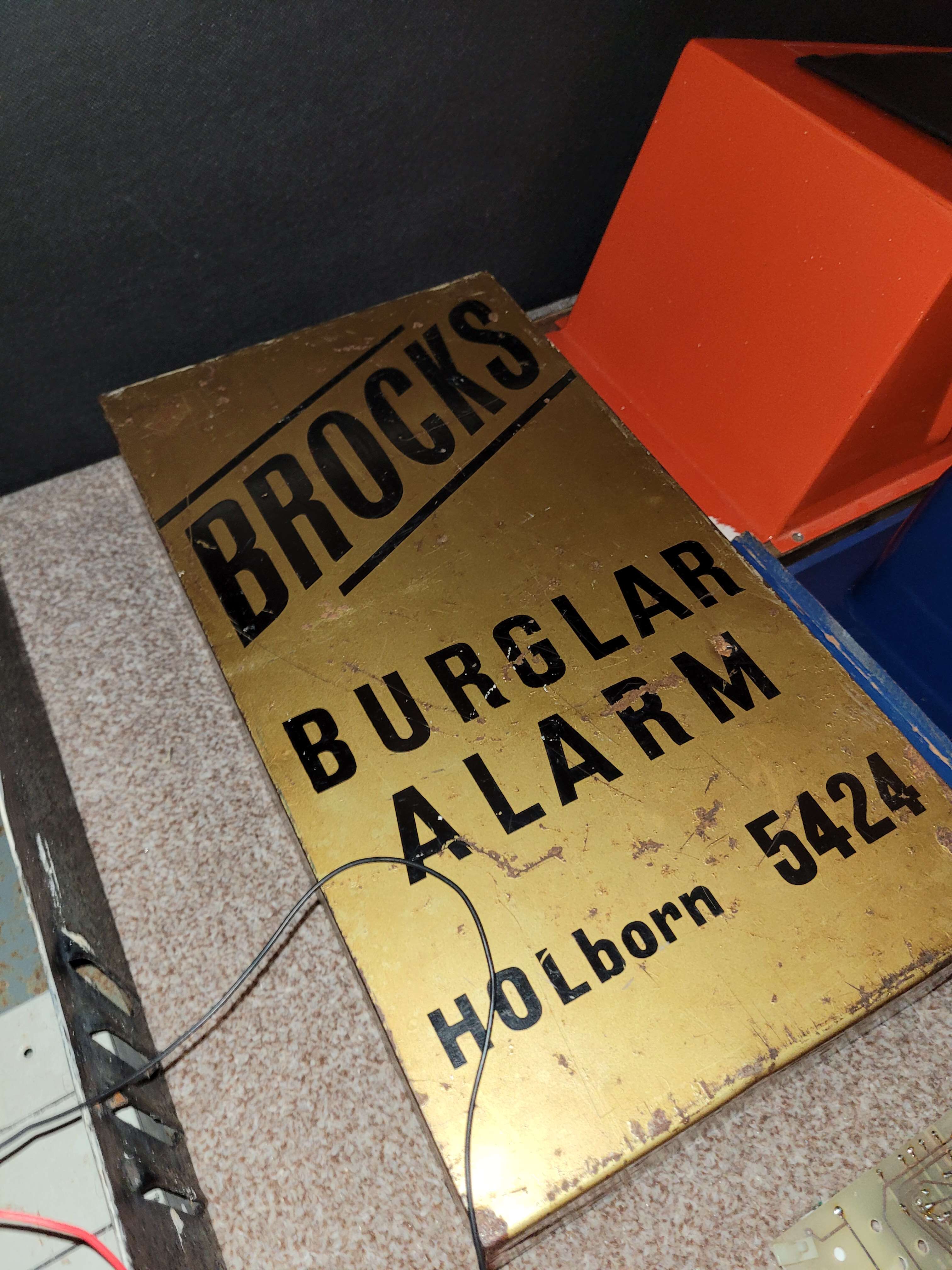
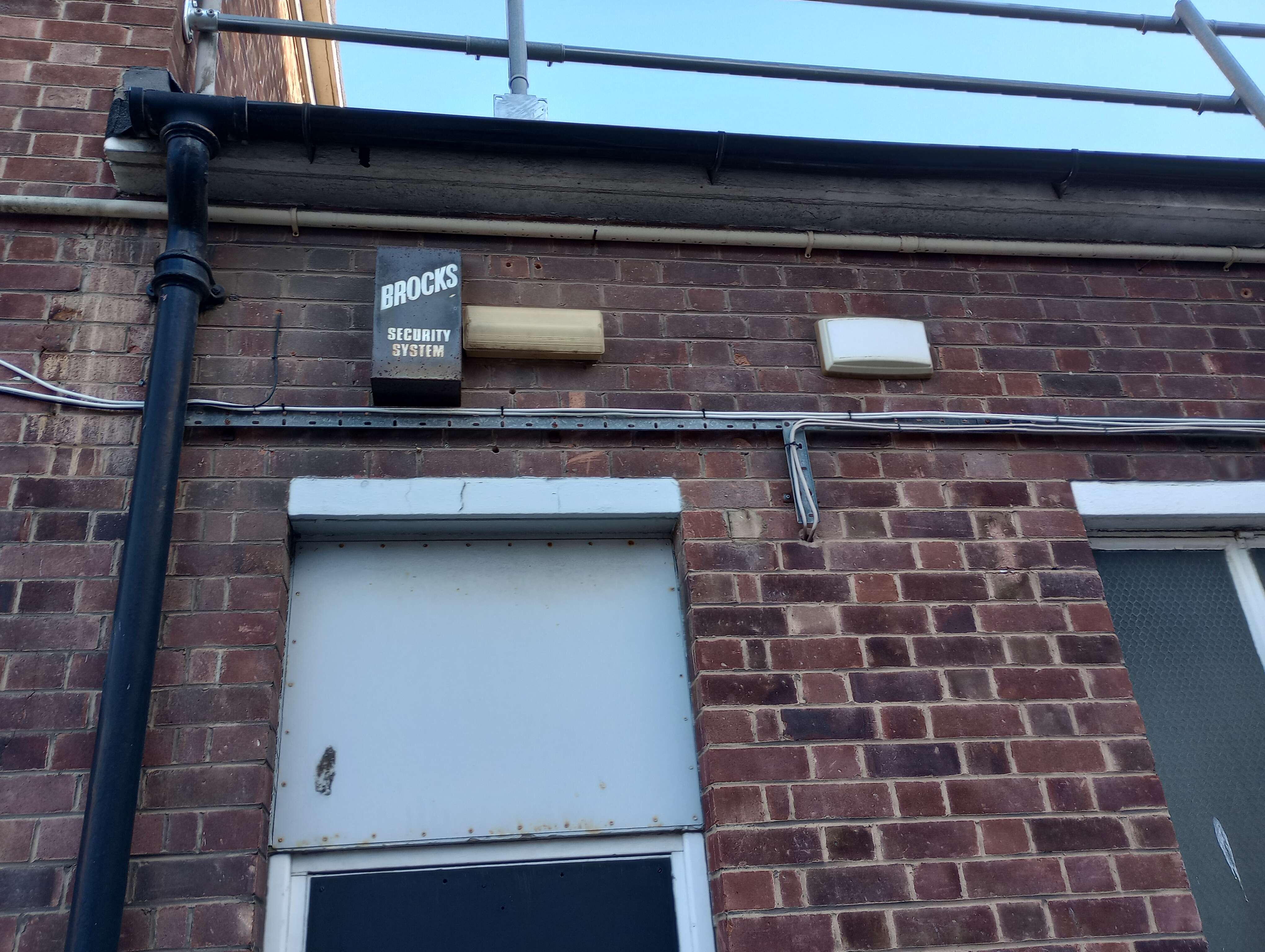
They are pretty modern looking, brocks seemed to always be ahead of the game. Look at two of the most well known companies in the industry, AFA and rely a bell; they were still hard wiring telephone relays whereas Brocks had circuit boards with transistorised circuits with built in bandit circuits and such. I've seen the diagram for the PC panels that came out around 1965/66, very very fancy technology wise for the time.
-
-
-
-
-
-
-
2 hours ago, sixwheeledbeast said:
No idea, never seen one.
T4 and 5 are just a link.
T8 and 9 are -ve rails, one would likely be for the bell.
Four top pins could have been SAB battery? One side of top pins is T6 the other is via the 1W resistor to -ve
It's the era I'd expect tamper switches to be microswitches with flying leads from terminals.
It would be logical to have all the field wiring on the first few terminals and the rest for the bell internals.
Originally i thought those solder joints had something to do with the battery but i couldn't think how it would. One side seems to go to the large resistor which is connected to the - VE. So i thought maby the solder joints is where the cover and rear tamper would go, then any additional tamper switches would go in T5 and T6 as T5 is shared with T4 and T6 goes to those pins.
As for T9 and 10, they had a link between them. Fell off though as the copper was weak.
-
Edited by Jack b
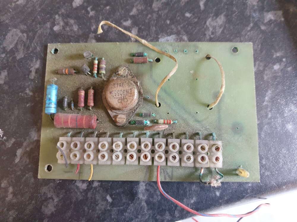
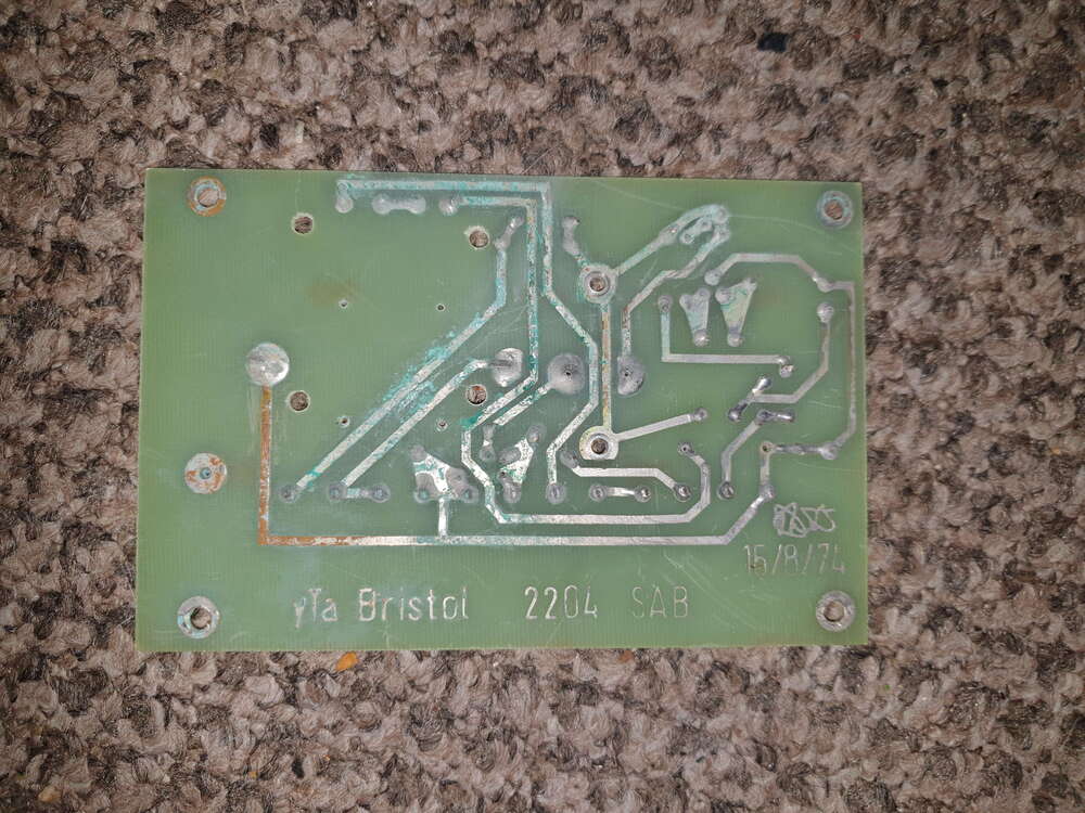
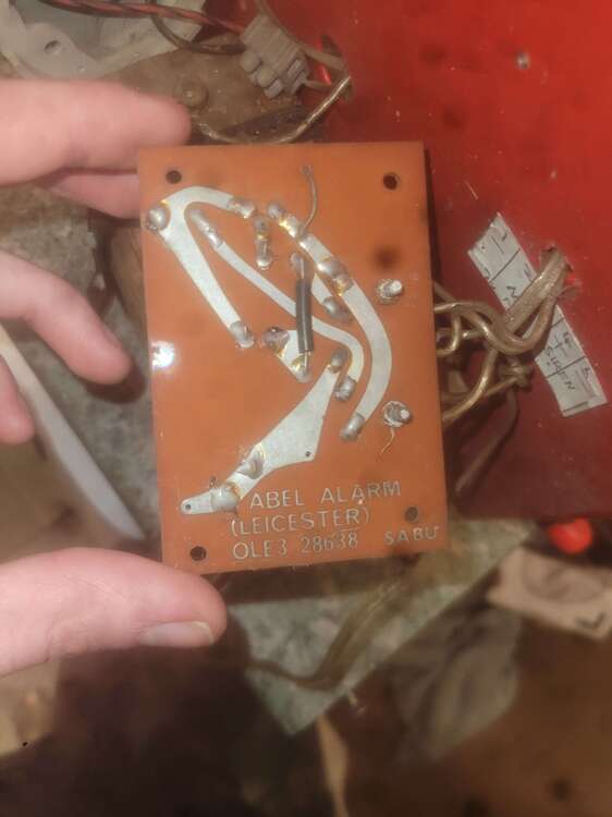
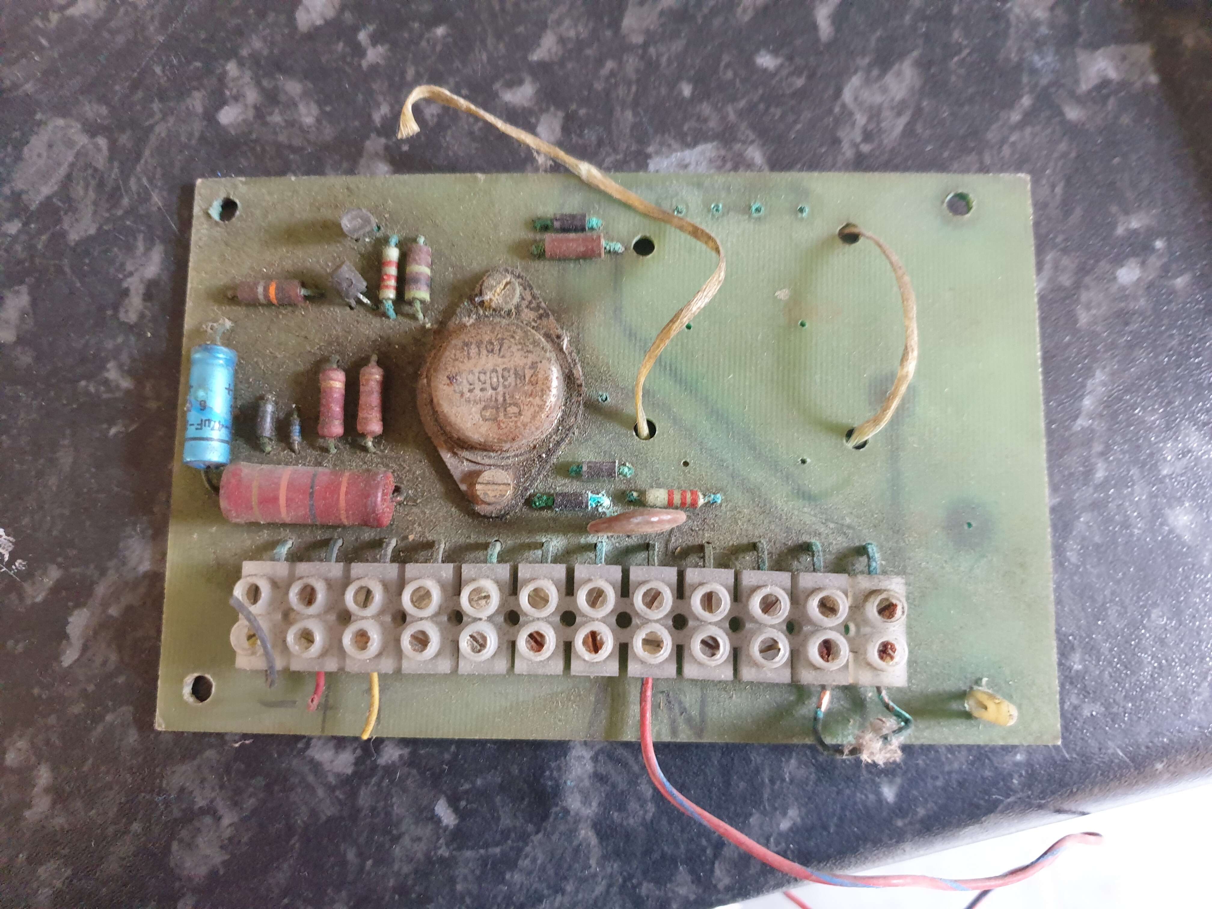
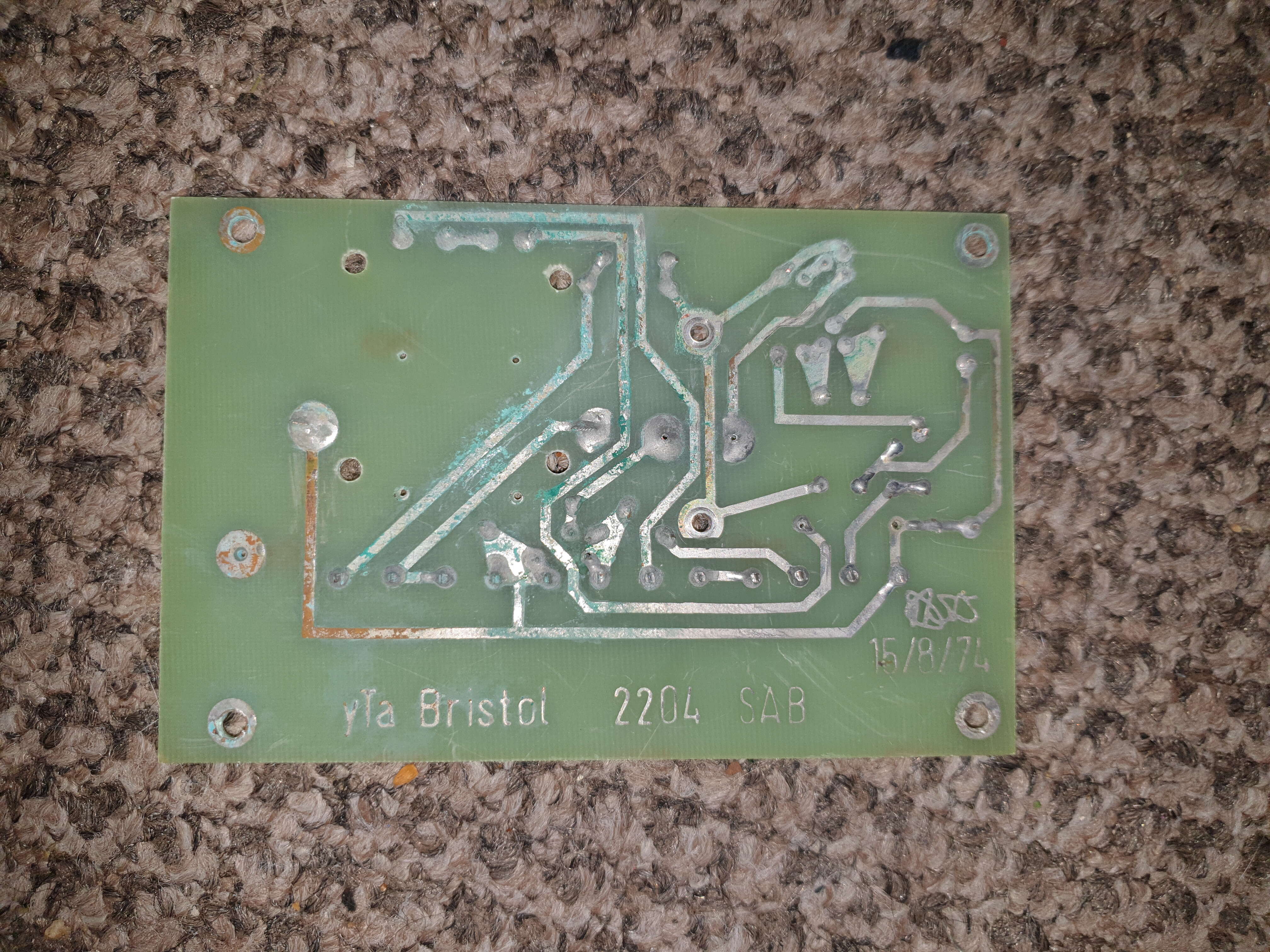
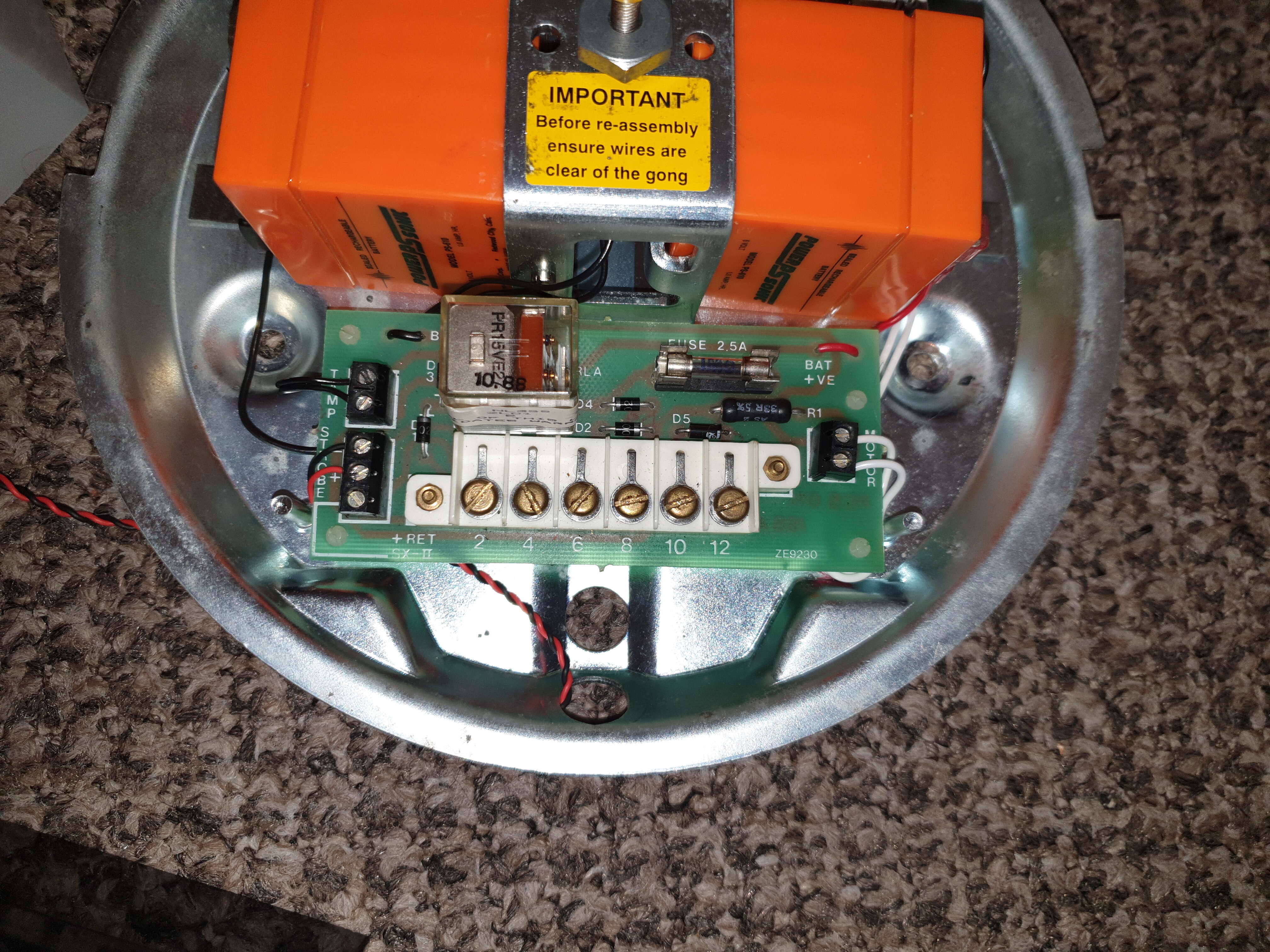
Hello, was wondering if anyone could tell me about this sab module? Found it in an SSW bell box; I've figured out most of the connections but there are still some that elude me.
This is what I've got so far
T1 - 0v
T2 - 12v
T3 - Positive trigger
T4 - Tamper return?
T5/T6 - Extra tamper?
T7/T8 - Bell
T9/T10 - Polarity link for tamp return?
T11/T12 - Battery enable
There's also 4 solder joints above where the battery was once fitted - is that where the tamper switches go?
Any help would be much appreciated.
-
-
-
-
Edited by Jack b
stupid autocorrectOn 15/07/2019 at 21:13, datadiffusion said:So you might have noticed back in the day a few Telecom Security boxes, the earlier ones of which had the famous post-81 British Telecom logo on.
https://burglaralarmbritain.wordpress.com/2013/07/18/telecom-security-southwark/
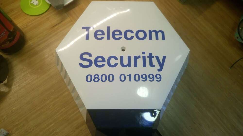
It seems they were bought by Modern Alarms but also seemed to be still around for a short time at least, by the time Modern themselves were rolled into ADT.
By the end they appeared to be using the same Galaxy systems as ADT, but with Telecom branding on the RKPs and the 'famous' coloured buttons for Police, Fire and Medical.
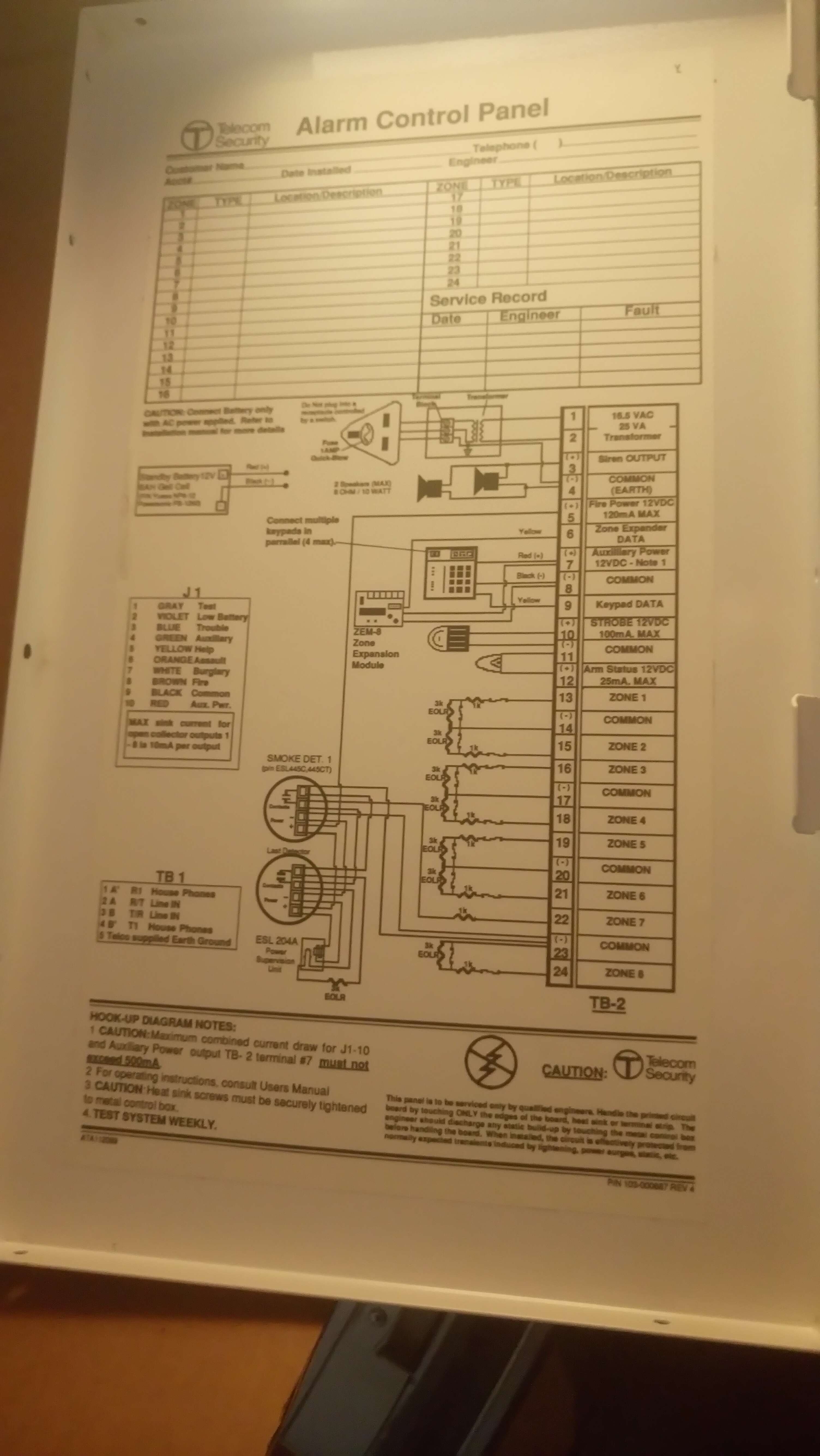
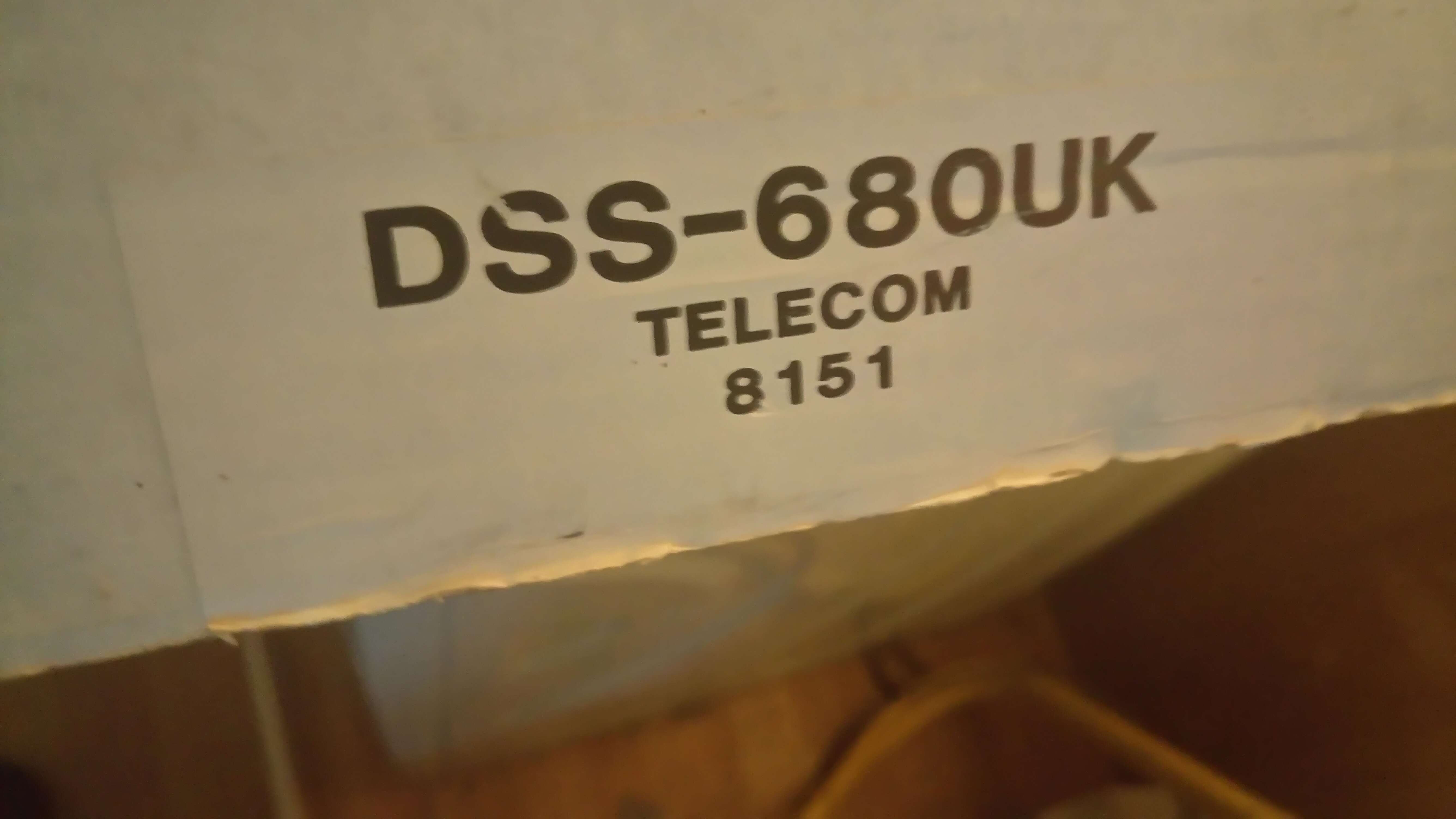
But what I've got hold of is one of the earlier, very definately not-available-in-shops Telecom alarms, brand new in it's box.
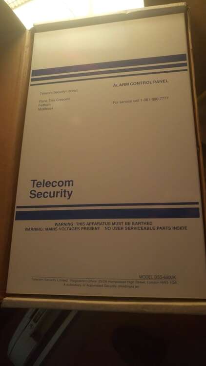
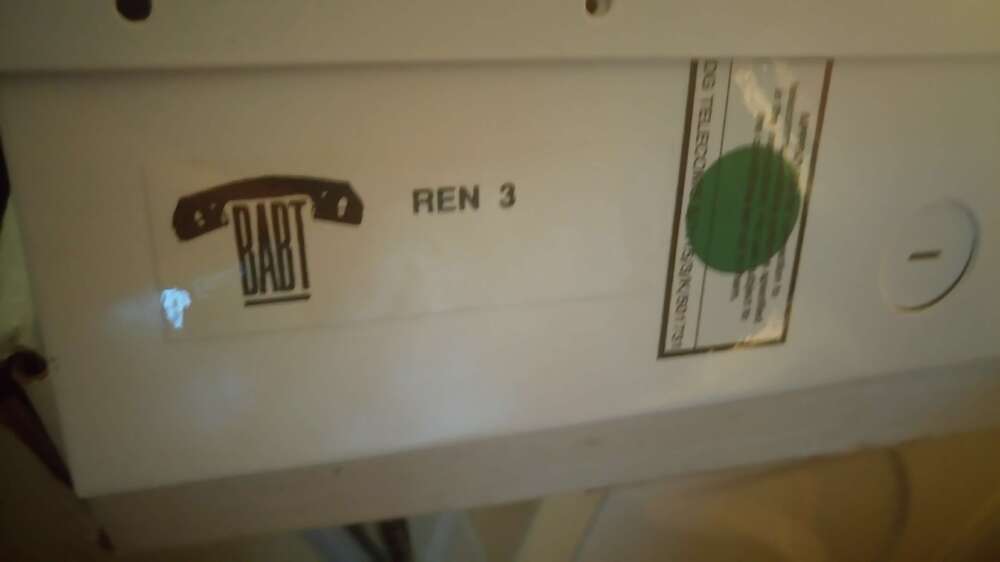
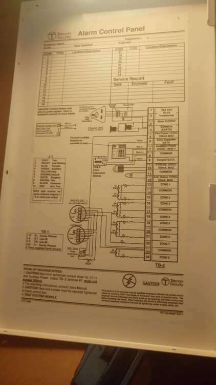
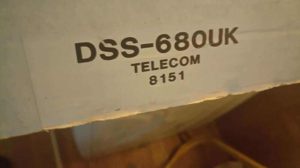
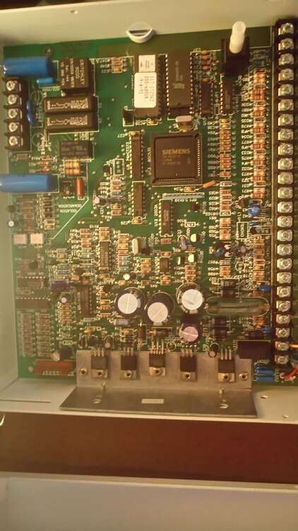
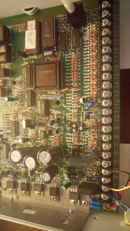
Note the BT logo but only on the inside. Very US looking, and would have had an external PSU and a keylock in the states too. However the
plug, rather than spur, connection is also very 'BT'. For some reason I'm assuming that these panels were never actually BS compliant, despite the
inferred police dispatch? Or did BT 'misuse' their ability to access 999 direct? It's certainly the only monitoring co. I've ever come across that will
call you an ambulance, other than specialist medical (non-security) monitoring? Note it can do up to 24 zones via expanders back when this was unheard of for
most panels especially a domestic aimed system.
This solves the 'mystery' of the Scantronic Telecom keypads being sold on eBay, I don't know what DSS stands for but I know that
Arrowhead* (see below) was a US company bought up by Scantronic Holdings in the early 90s. It went as badly as you can imagine and is pretty much
how Scanny fell into the hands of US buyers (Cooper) the first time round with Arrowhead (seemingly partially rebranded to Scantronic by then)
being essentially written off for pennies.
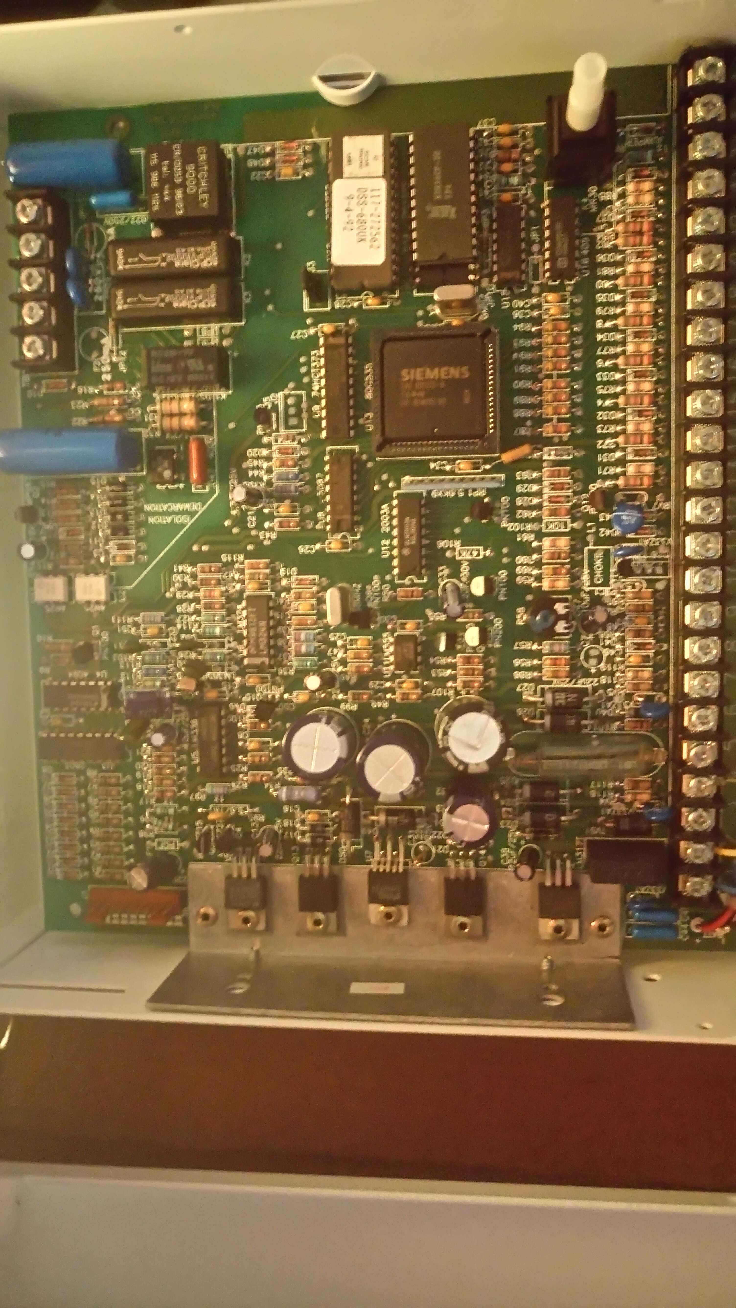
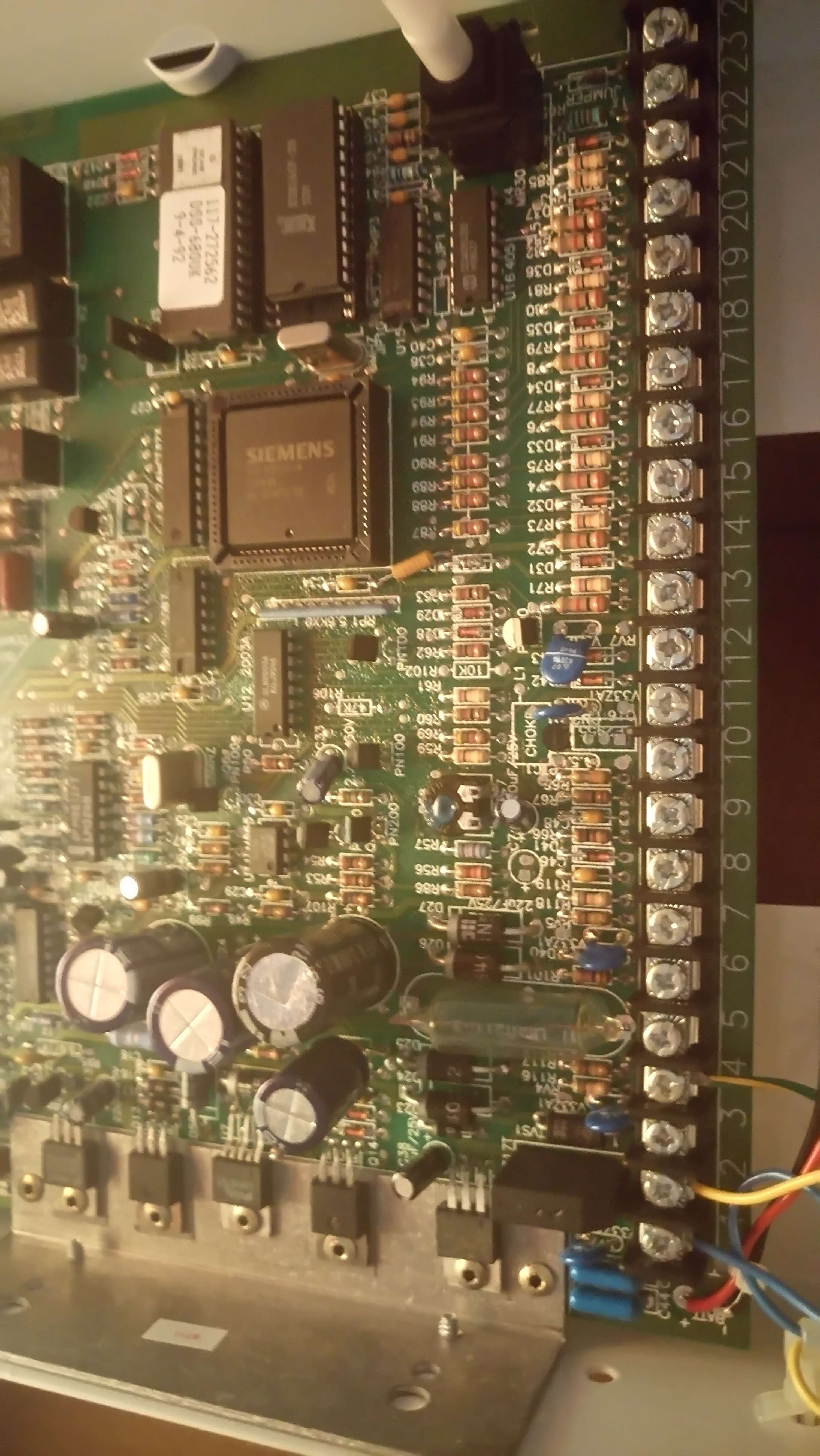
In fact, take a look at the panel closely and you'll see a Scan Tronic label on one of the ICs. I'm impressed by that Siemens CPU too.
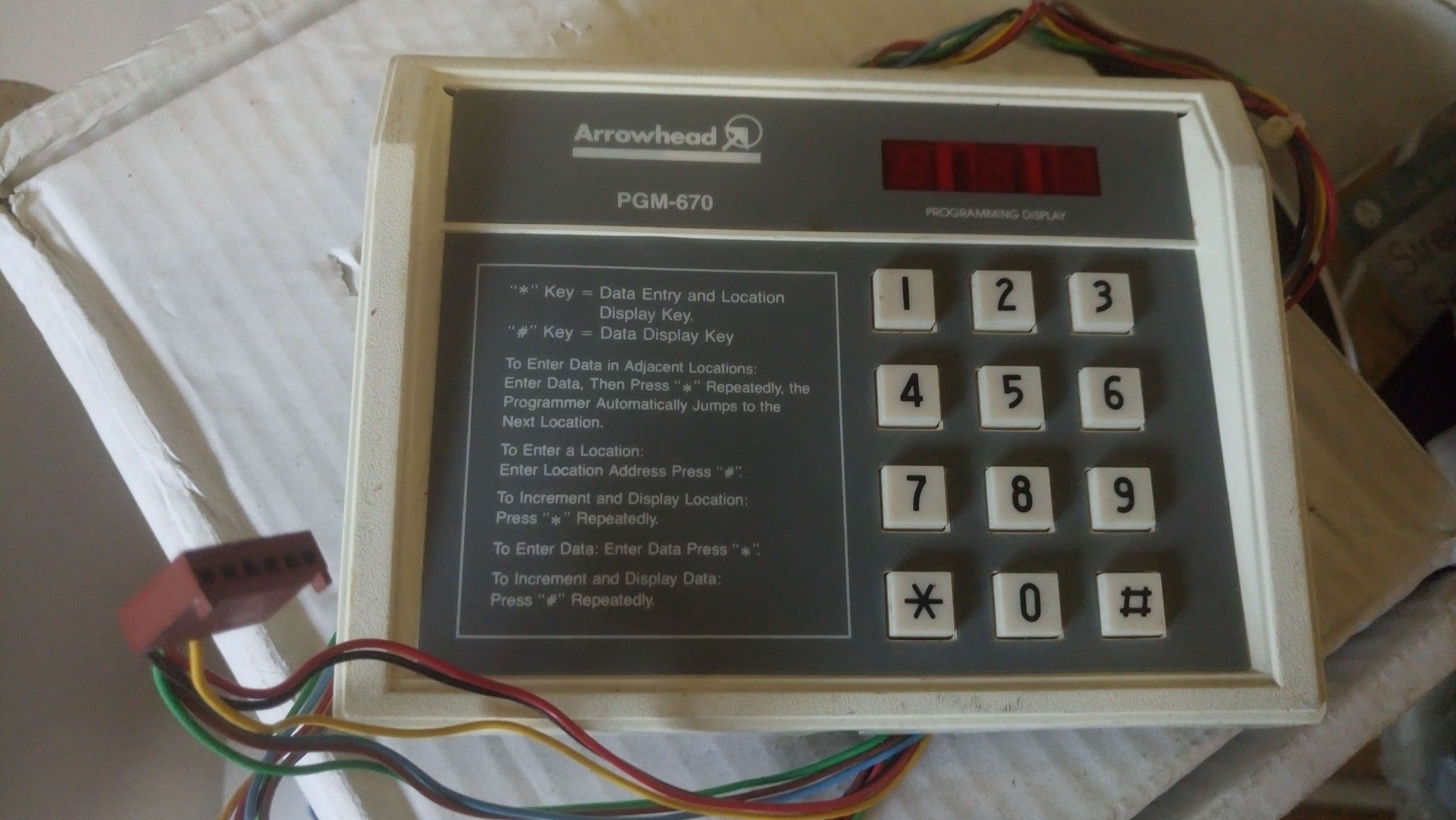
I don;t have a keyboard but this little bundle came with something I've never seen before on ebay - an Arrowhead programming keyboard!
It's just like the eBay link above, but with 3 LEDs not two, and 3 extra wires and a plug.
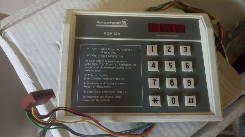
Unfortunately, there is no-where to plug it onto this unit.
So, for now the adventure stops.
Were these programmed remotely (as it was a monitored-only service) or only via the remote? I suppose it could have been done via a 2 digit RKP, after all the 9800 is.
Does anyone know anything about these....?
How large is that panel? I should be getting a telecom security box soon and if the panel isn't too large then i might look for one on ebay.
-
-
-
-
-
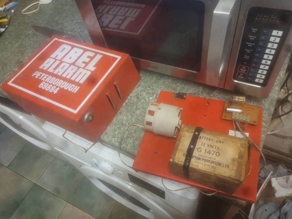

ABEL Alarm from 1972
in Vintage General Discussion
Yeah, it's quite old. I didn't think the bell box design dated back that early. Plus it's plastic coated so I thought maby mid to late 70s