

Gabs
-
Posts
292 -
Joined
-
Last visited
Content Type
Profiles
Forums
Events
Downloads
Gallery
Blogs
Posts posted by Gabs
-
-
16 minutes ago, MrHappy said:
Revann Electronics ?
Yes, I think so. Why?
-
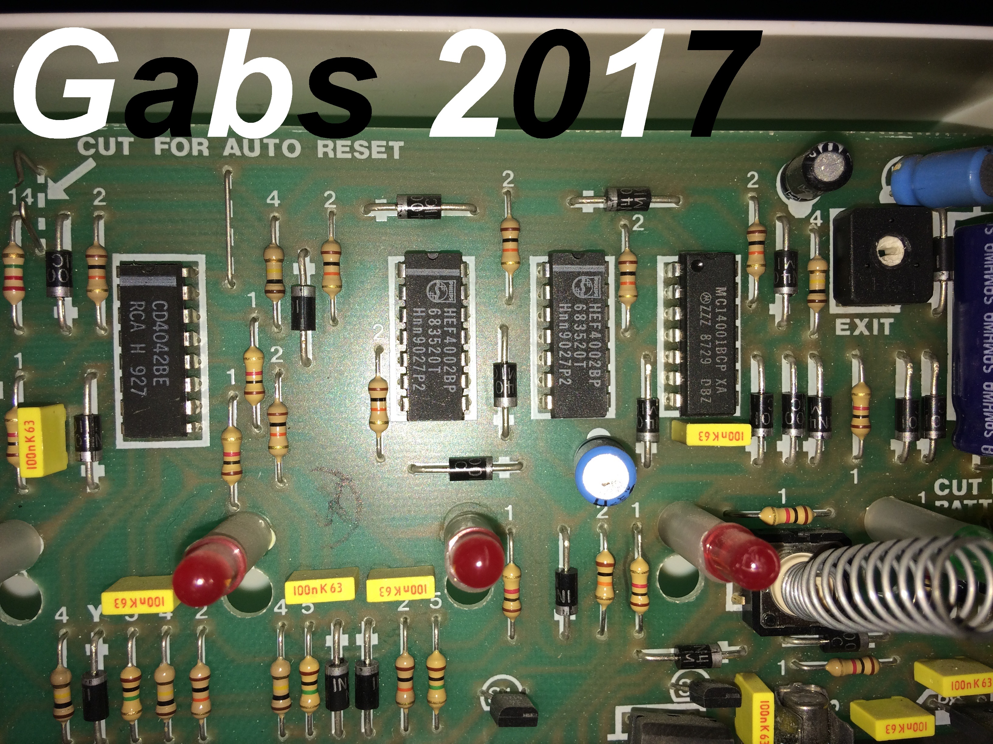
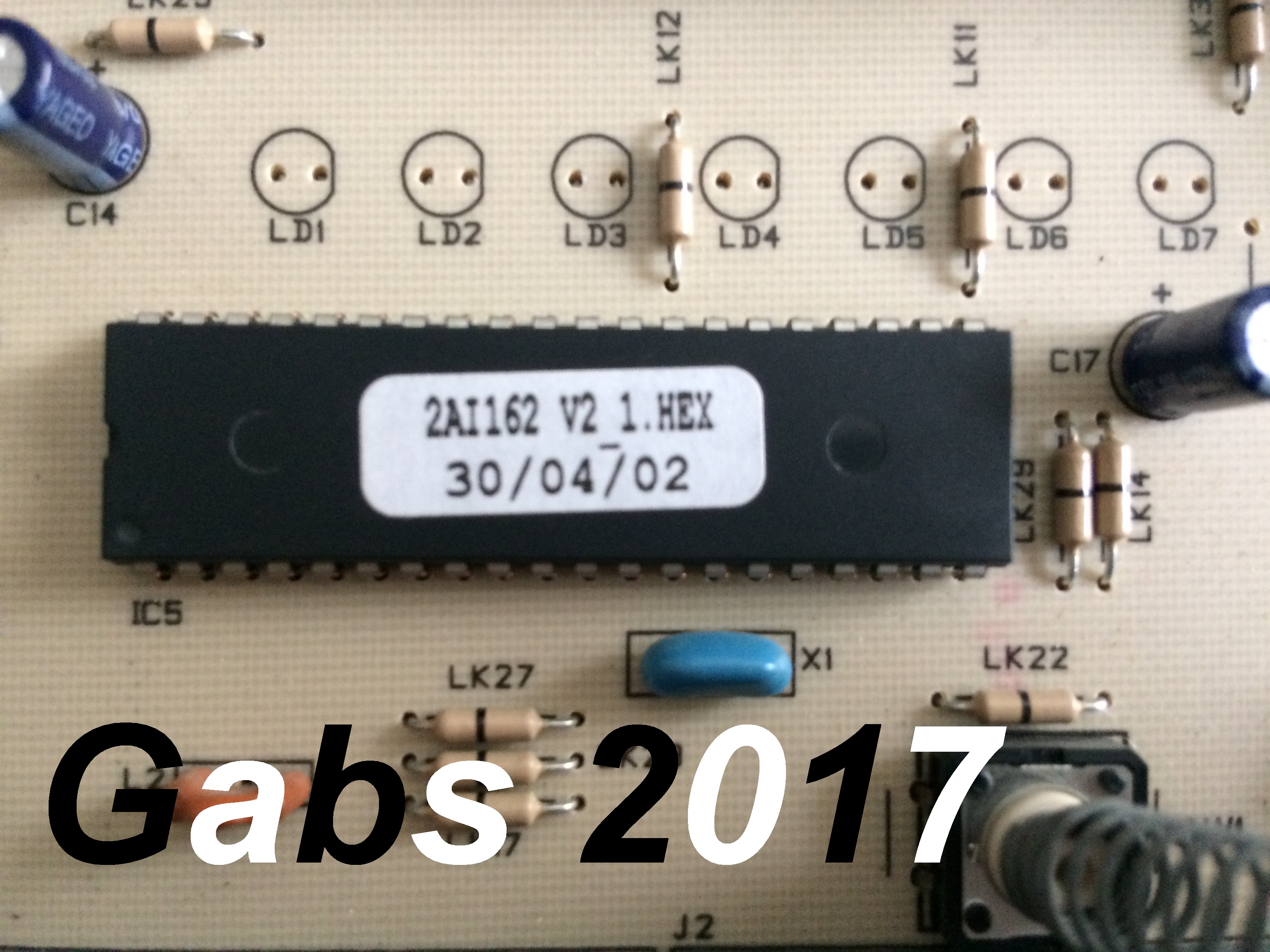
got these two photos of a very old one I have, but its not brilliant, that's why I'm setting myself the challenge to design and make a new one

-
22 hours ago, sixwheeledbeast said:
I doubt a picture of an SAB module would be much help, most are painted and you wouldn't be able to work out the traces.
I also wouldn't expect for the alarm you are making you need to go into that much depth either.
This is a circuit with some basic components (including my favourite the 555) that you may want to look at for a charging circuit.
http://www.edutek.ltd.uk/Binaries/Circuits/Li-ion_battery_charger.pdf
The Op-Amp need 3V head minimum, so if your charging a 7.2V NiCd on a 12Vdc supply you will be fine to adjust the values to suit.
I assume you used a CD4069 Hex Inverter chip for your flasher?
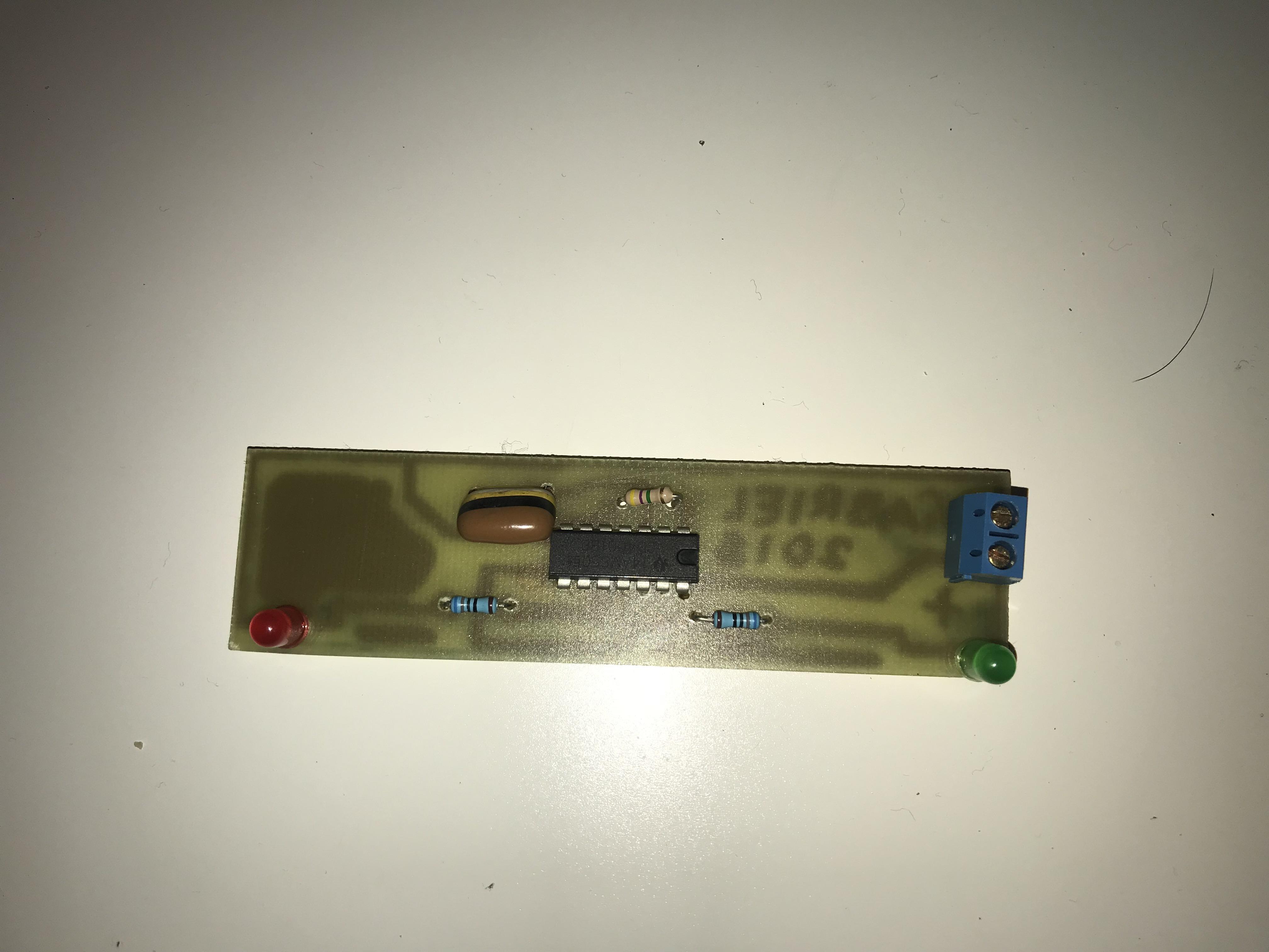
Thanks for the reply. I actually used a CMOS 4001 chip, and it worked pretty well. I was thinking of using a betray like this: https://uk.rs-online.com/web/p/coin-button-rechargeable-batteries/0525815/ bit safer than a Lithium one.
12 hours ago, Nova-Security said:I would have gone with a 4017 mono stable everything built in
Did have a SAB diagram somewhere will have a look
Thanks, I'd appreciate that, I have a basic circuit design, just not sure of it at the moment.
-
Some time ago, I was directed to this site http://www.zen22142.zen.co.uk/ronj/shs.html when asking about an alarm panel schematic, I am in the process of building a panel from this website, however, I was wondering if anyone had a schematic I can use to make an SAB module, or bell module, or even if they have one would be able to get a photo of its PCB tracks, and components, so I could have a go at tracing them back out. I have an idea for a circuit, its the Ni-Cd battery charging bit I'm unsure of, any help would be much appreciated. I have included a photo of a CMOS LED flasher I made, this could be the comfort LEDs of the bell box,
Gabs
-
16 minutes ago, MrHappy said:
IMHO the school was a f'kin zoo, the pupils would have been better going straight to the workplace (or prison)
Apart from the alarm which I think was GSCE.... CDT memories
a) Teacher did'nt like the smell of old spice as it reminded thing of someone dieing from cancer - que 30 kids bathing in old spice aftershave.
b) I nailed a load of text books to the work benches, open cover wack in a big clout nail though the book, close cover.
I must have done 3 or 4 terms of that's all I can recall
Sounds very reminiscent of my school, that I have just left. I took product design as a GCSE, but was never given the task to do anything as exciting as make my own alarm panel. Do you have any pictures of the alarm panel that you made? I'd be interested to see
Sounds like a funny thing to do, although it would ruin the books
-
28 minutes ago, norman said:
Not sure, nothing old and ancient. A few components maybe.
That's good
I have decided that I will probably build one of the transistor panels from Ron's site, so the components will help me there, thanks
26 minutes ago, datadiffusion said:Yarp but at least it has a full description of what's going on, which is pretty cool.
Yeah, it is. Shame Velleman don't make alarm kits, they mainly do things to do with lighting, so not as good.
-
17 minutes ago, datadiffusion said:
Merry Xmas
5 zone alarm panel with circuit and everything - https://www.quasarelectronics.co.uk/kit-files/smart-kit/1094.pdf
Download and save before they remove it (it's been discontinued, a bit like my boat...)
Replacement (but seems to use custom IC) - https://www.quasarelectronics.co.uk/Item/smart-kit-1140-five-zone-alarm-system (and is also EOL!)
Thanks, I'll have a look at that, schematic looks pretty big though, more complex than the Logic 4
-
16 hours ago, norman said:
@Gabs I'll have a look in my garage tomorrow, I'm sure I have some bits and pieces that you could make use of. When I've checked I'll pm you. You can have them foc of course.
What bits and pieces do you have? Old components, panels? Or just a mixture of things? Just curious, before I go off to Maplin and buy some Transistors for a Circuit on Ron's site
-
2 hours ago, MrHappy said:
made something a school project with a 24way jb box as the case,
& was accused of buying it rather than making it
That's bad that you were accused of buying it, but it also says it was better than anything the teacher was expecting.
2 hours ago, norman said:I made a continuity tester thing, made it in a circular casing all vacuum formed.
With old parts, if I make my own panel, I'll have a go at vacuum forming a casing for it, would be rather rewarding to do, making the panel from scratch.
-
10 minutes ago, MrHappy said:
I think plastics where much cheaper to produce & ship than metal cabinets.
Yeah, would weigh much less. Have you ever tried making your own alarm panel?
-
13 minutes ago, MrHappy said:
Its was very basic & rather cheap, its along time ago but IIRC most where metal boxed & quite bit dearer
lol
Yeah, the metal ones seemed to offer much greater security than the plastic ones. Although the plastic ones look nicer, well, as nice as a black and white plastic box can look.
14 minutes ago, MrHappy said:seen a 9825 painted silver (ewe)
Think white is the best colour for a panel
-
11 hours ago, MrHappy said:
late 80's / early 90's £34+vat or there abouts ?
Cheaper than the Accentas then. I can see why it cost that, I guess a lot of thinking and design went in to it.
11 hours ago, norman said:@Gabs I'll have a look in my garage tomorrow, I'm sure I have some bits and pieces that you could make use of. When I've checked I'll pm you. You can have them foc of course.
Thanks, that'd be great. I always have this tab open, so I'll just check my PM every now and again.
9 hours ago, james.wilson said:ill have a look, i might have some old f130's etc.
good to see a keen mind
Thanks, I have always been interested in this sort of stuff, I was thinking of building something like this http://www.bentleysecurity.com/ that my be more simple.
-
1 hour ago, sixwheeledbeast said:
RonJ has some good schematics on his site I have used some of them before.
From what you say in your posts you seem interested in the electronics but never build much before?
If this is the case take a look at Ron's smaller and simpler transistor circuits first, before you build up to the modular one posted.
The IC's are all pretty standard CMOS 4xxx Series, cheap and easy to pick up. I wouldn't start reverse engineering a Logic 4 as your first project tho.
Wow, thanks for the replies guys
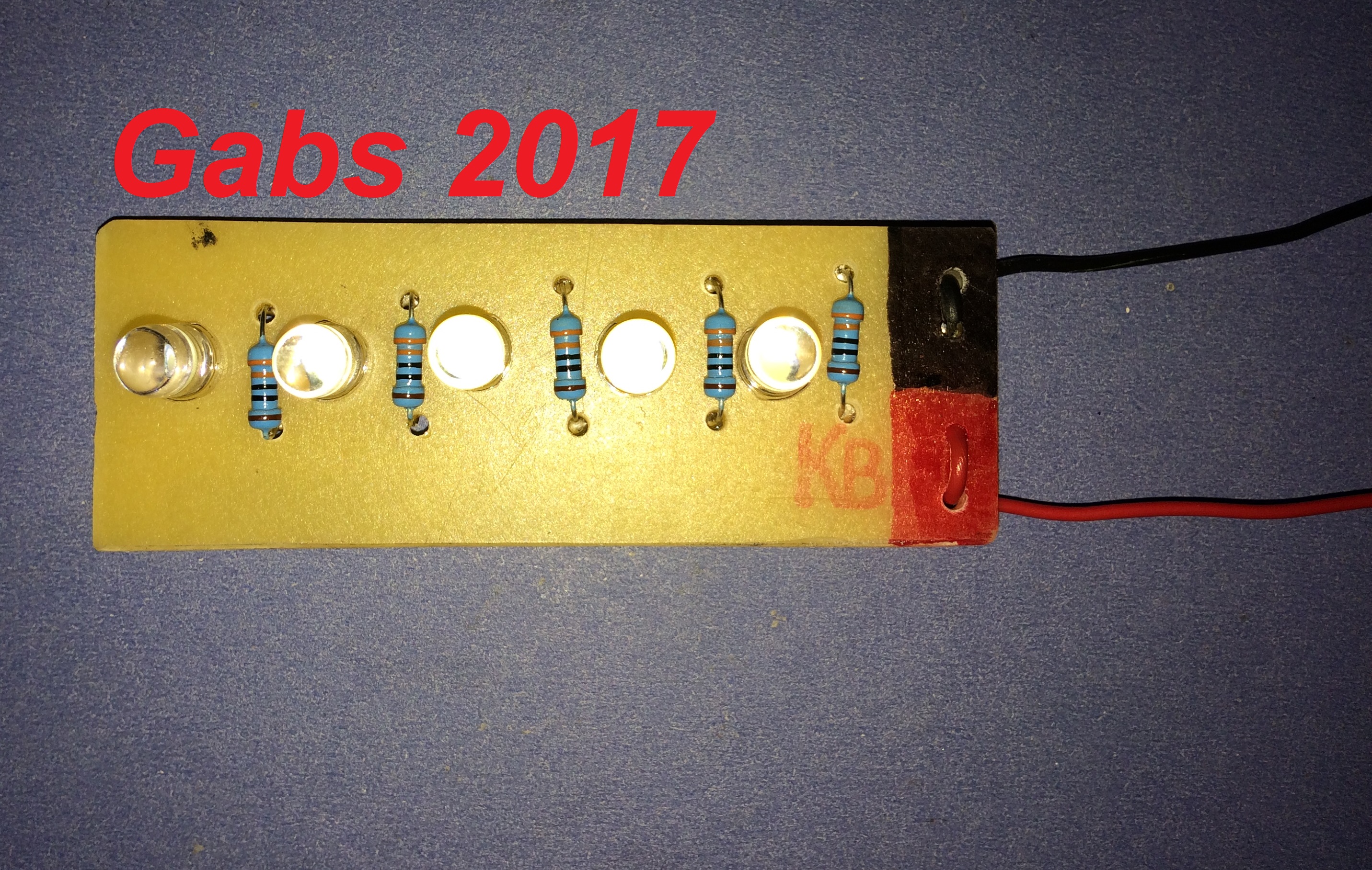
I will look on his site, I actually have been using and learning with my Arduino Microcontroller, in this picture, it is connected to my Accenta G3, I made a Mission Impossible stile beam break detector hooked up to Zone 4, so an instant alarm when set. I will have a go at some projects from his site tomorrow before I take on the Logic 4, which was probably designed by an engineer with a lot more experience than 16 year old me I have built sme things, I etch my own PCBs as well, to put my very small projects on. I'll also add a picture of a PCB that I have made, it was designed to be an LED version of a Airbus A320 wing strobe
1 hour ago, GalaxyGuy said:No, just 4000 series chips. Pretty old technology and similar to the circuits posted earlier, but will give you a better understanding of the electronics if you can build and debug the circuit.
The microprocessor based stuff these days works by multiplexed analog to digital conversion. The zones are analog potential dividers, with the resulting voltage (from the zone) being converted to digital and read by the CPU.
Ah, the microprocessor stuff does sound much more complex, I'll stick to the basic ICs for now
And let my knowledge rise first.
1 hour ago, GalaxyGuy said:Agree with SWB. Learn basic electronics. Transistors, gates, flip flops, RC timers, Etc. There used to be project kits with many circuit possibilities years ago - they were basic, but very good. The Tandy 200 in 1 was my dream x-mas present when I was 9 y/o. I don't think I ever played with any toy more than that.
After that, skip the alarm circuit and jump to Raspberry Pi I/O. You'll find it easier to learn/modify programming rather than the example alarm circuits, but you still need the grounding (no pun intended) in basic electronics.
I actually have a kit similar to the Tandy one, it was my Dad's he gave to me at quite a young age, before I started messing on with proper alarm panels. I have an Arduino microcontroller, which I made wok with my ADE simple set reader, which as fun, thy worked together really well, making the Arduino control a siren, depending on the relay state of the set reader.
45 minutes ago, sixwheeledbeast said:Exactly, just like I said in my first post. It's good to have knowledge of the basics, so start small but also consider tech moves on.
Back when Logic 4's where designed a office desktop computer had less power than a SBC's you can buy now. A RPi3 is about £30, wouldn't like to guess what a P5 Pentium system or the like would have cost.
The other benefit is if you get bored of the project you can easily repurpose the SBC for the next project.
If you are really interested in making up some circuits maybe try some basic timer circuits to start, 555 timers are normally good to cut your teeth on.
They are very easy to build a working project and if wired in the different modes, give good understanding of RC networks, transistors and logic level.
This is assuming you are starting from minimal electronics knowledge of course.
I know, I would be quite interested actually o see how the Logic 4 and Optimas were designed, the PCBs have quite clearly been designed by a computer program, although I do not know of any PCB design programs existing back in the early 1990s. I have just ordered 50 555 timer chips, so hopefully I'll be able to design something good with them, and other chips I have.
36 minutes ago, datadiffusion said:Interesting, simpler in number and function than I'd ever imagined.
When I started in this lark you could still buy the Logic 4, but the multizone LCD path was one the Co I worked took from the outset, thankfully.
Otherwise as above basics then look up a few circuits to build yourself. You'll probably find one of those 200-in1 electronics type kits on eBay for pennies.
I guess they were designed with simplicity for the user in mind, that's what I like about ADE, nothing is ever too hard to do on their panels.
How much was the Logic 4 at the time?
-
 1
1
-
-
2 hours ago, MrHappy said:
I'd thought a keen young mind would be able to copy an old logic 4 or similar ?
I actually have just got a Logic 4, it looks really quite complex, I could give it a go, but I am not sure if it would work.
2 hours ago, datadiffusion said:Presumably still uses custom IC's though?
Pretty sure even the CPA2 panel had a custom IC in it (possibly just for speaker sounds / tones though).
As for my 6 zone electronics kit (actually might have been 5), google is your friend (I forget the make), though you'll have to wade through all the basic 1 zone ones
Here are the 4 ICs in the Logic 4, not sure if any are custom made for ADE, would anyone else know? If not, there is a chance I will try to make/copy the board traces for the Logic 4
2 hours ago, Nova-Security said:before you start with PICs you need to look at the basics.
I'll have a look at that, thanks
-
Thanks for the replies, I just thought using a micro-controller may have been easier than using more passive components, such as individual logic ICs.
5 hours ago, datadiffusion said:For various reasons I bought a 6 zone alarm PCB 'kit' for my narrowboat (mainly related to wanting a low current panel with multiple latching zones that ran off 12V without looking for a 50hz signal to run a clock).
I am pretty sure it came with a comprehensive description and everything, like these kind of kits do.
Googling should find it.
What sort of kit was it? I'd be interested to know, and maybe try to build one. The description part also sounds helpful
-
Does anyone have, or know where I can get a schematic for any alarm panel, (Preferably ADE), reason for me asking, I am very interested in engineering and how these panels were designed.I was thinking about making my own panel, using an ATMEL microprocessor, and a custom made PCB. I was mainly interested in seeing how the zones and inputs are connected to the main microprocessor of the control panel (Picture shows what I am assuming to be the PIC microcontroller of an Accenta G3) I'm also interested din the software that the alarm panels run as well, so if anyone knows a little about how they are programmed and what language is used, I'd really appreciate it
Thanks In Advance
-
On 09/07/2017 at 01:09, james.wilson said:
Elmdene make good stuff but why do you want such an old bit of kit?
I collect the older, more rare alarms, and do my best to restore them and make them work again
-
Just now, james.wilson said:
just get a new sab. Your trying to get blackberry 1 working
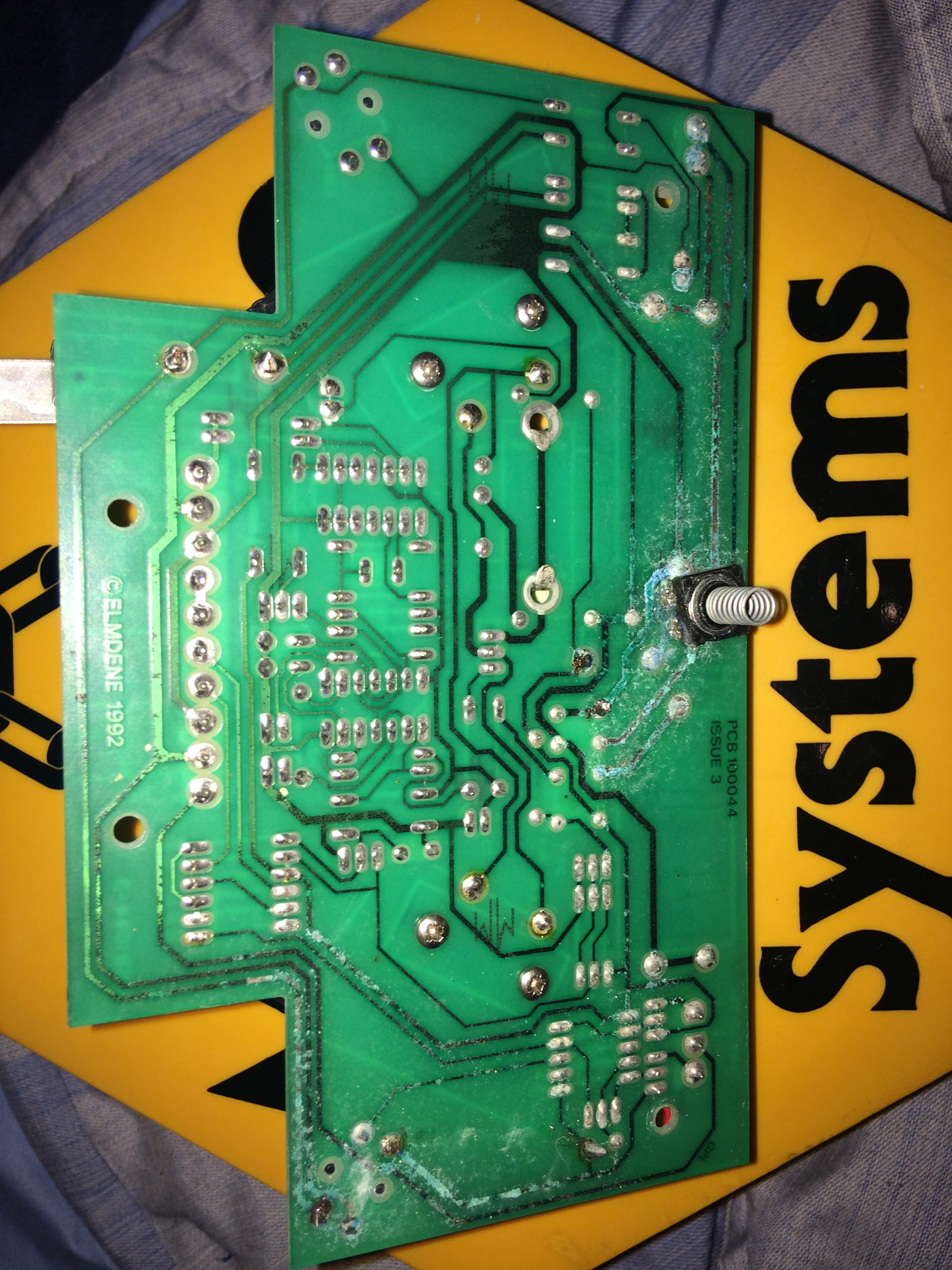
Good idea. Where do I get an SAB, though? Ha, it is the alarm equivalent, very old indeed. First Piezo box? Board says 'ELMDENE 1992'
-
5 hours ago, MrHappy said:
shouldn't a young man like you be drinking cider or sniffing glue in the park ?
its old tat but try-
close the 3 tamper switches - bolt, bottom & back
leave the 2 anti foam switches open
add hold off voltage, with tampers close it should be silent
if so, wire link from rtn to & it should ring ?
Well, I go out with my friends, don't worry... I'm not THAT sad
I tried all of that, but it didn't really work. Do you have any idea where I could get a Eurobell module? That is my next hope
-
1
-
-
10 hours ago, The Arab said:
If you're just putting power on are you holding the tamper switches down as from memory the things sounded when you put power on till the tamper switches are closed, also watch the big white paddles as they were for anti foam and caused nothing but hassle so slide them off
Well, I am trying to hold them down, but it wont stop, I am n ot really bothered about any of that working, all I want is it to sound at full volume when power is applied
9 hours ago, datadiffusion said:Rear tamper switch looks goosed to me.
Yeah, they are are... Sadly. Do you think to get the volume of it up, I could use something like this: http://www.ebay.co.uk/itm/LM386-Super-Mini-Amplifier-Board-Module-3V-12V-Kit-Red-Led-Light-Blue-PC-Board/252628203210?_trksid=p2047675.c100005.m1851&_trkparms=aid%3D222007%26algo%3DSIM.MBE%26ao%3D2%26asc%3D44779%26meid%3D597b9836e54d40ae8cef13a9609a3762%26pid%3D100005%26rk%3D6%26rkt%3D6%26sd%3D332261893488 I am thinking of it.
20 hours ago, norman said:Could be the batteries dragging it down, but I'd take the engineer link out first and try again.
I removed them... no difference
-
11 minutes ago, norman said:
Could be the batteries dragging it down, but I'd take the engineer link out first and try again.
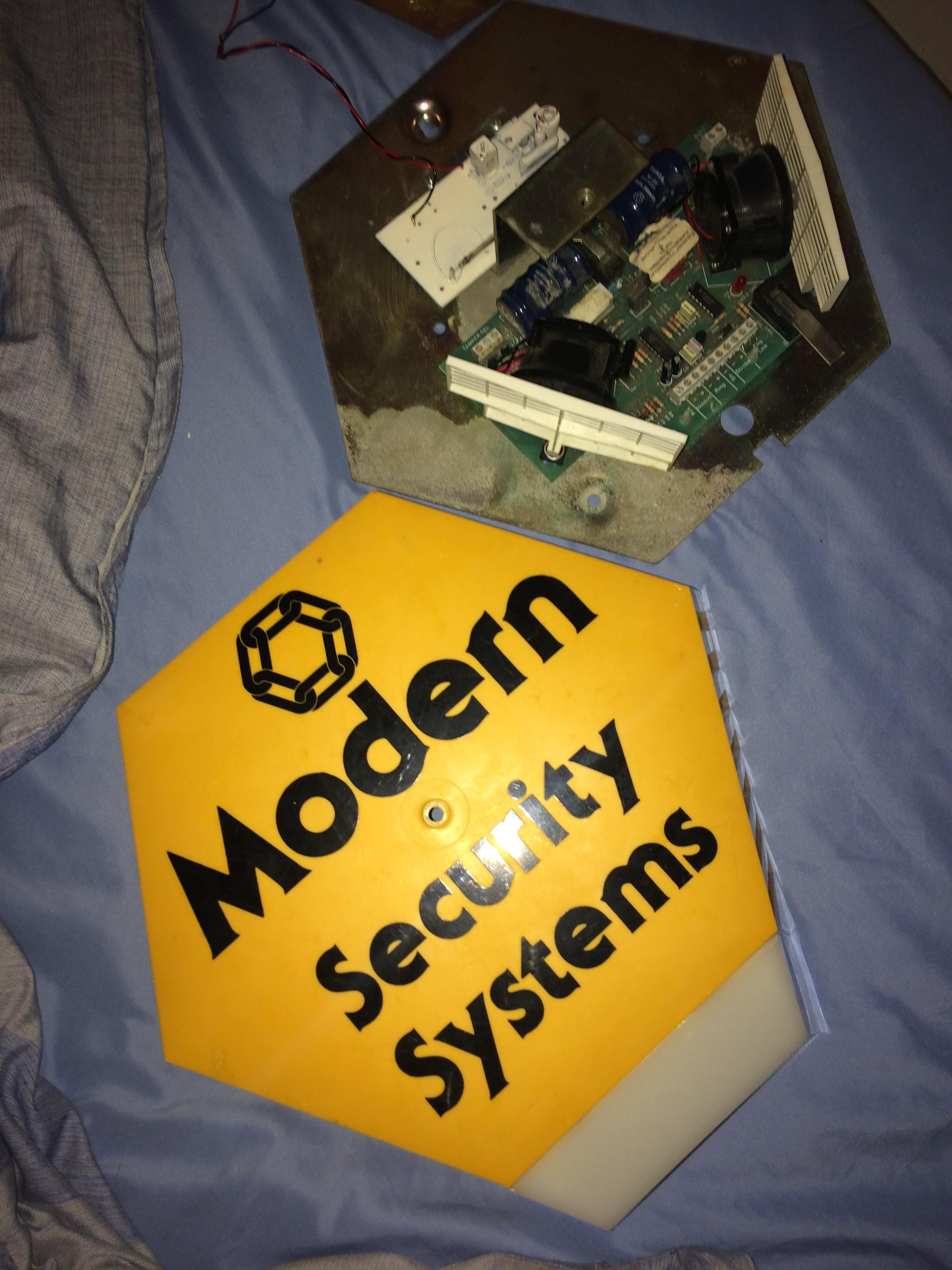
I tried that, and it made no difference. I'll try removing the batteries and try it again. It's a nice bell box, shame Modern are no longer around. What does the Engineer link do?
Just now, james.wilson said:looking the pcb it don't look the best
I know, that was my concern, it may be damaged beyond repair. I'll have a go at removing the batteries and try it again
-
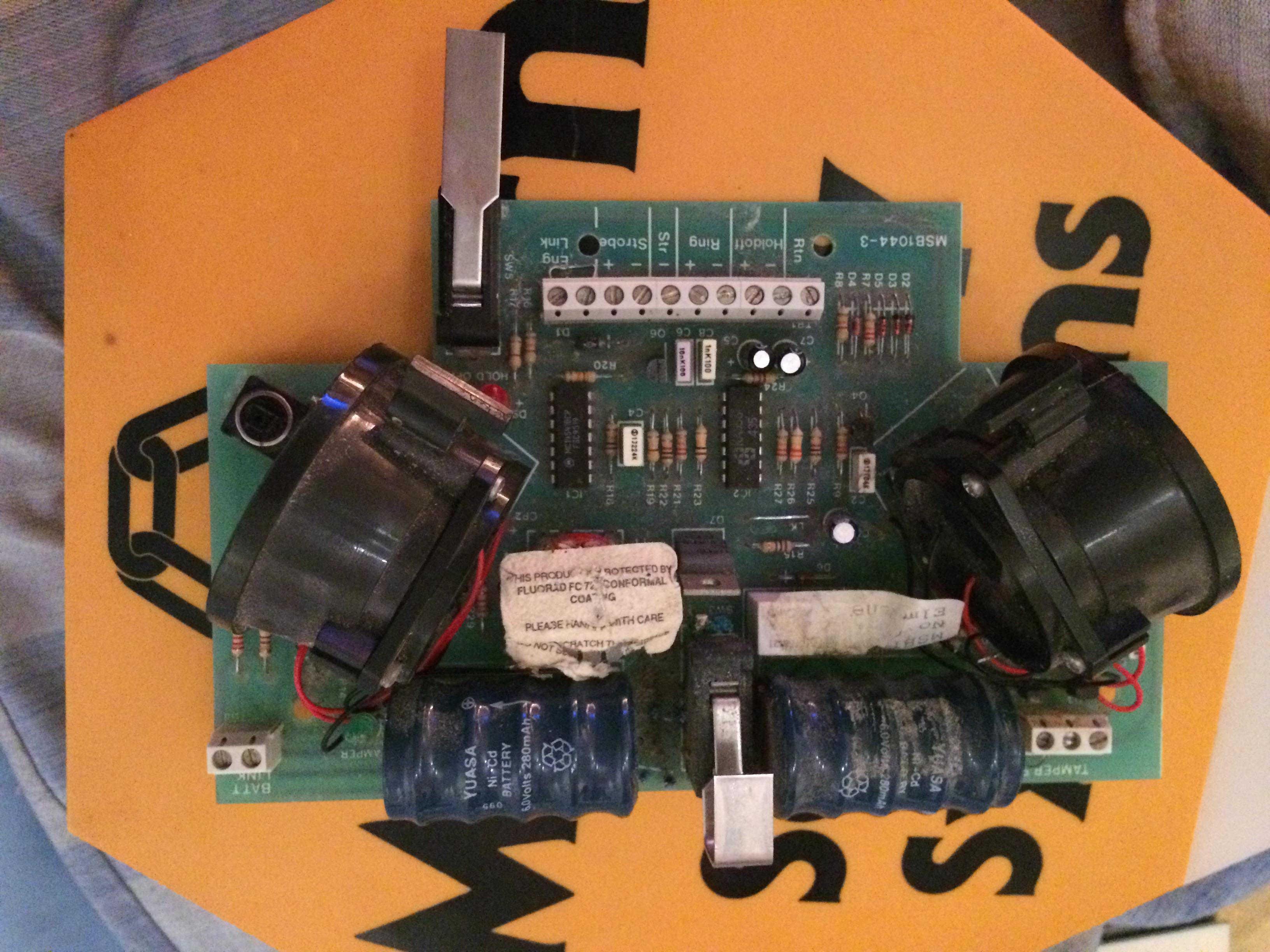
I have just got a new Modern Security Systems bell box, made by Elmdene, dated 1992, however when power is applied, both sirens will sound very quietly, not at full power t all. Is this a problem with the bell box, or the wiring? I just put 12V into the Hold Off and it started sounding very quietly. Does anyone know if this has SAB/SCB functionality, or is it just SAB? If it is SCB, i know that it is the batteries that are the problem, I just need to change it back to SAB somehow, if this is the case.
Thanks In Advance
-
14 minutes ago, MrHappy said:
kinda like somebody getting hold ot the keys for your house with a prox token on them ?
I guess so, didn't think of that lol
8 minutes ago, james.wilson said:most apps require you to enter a valid user code to use. Plus you can use the lock on the phone. Just don't write the code and your address on your phone!
Didn't think of that, wither. I was just curious, I need to get myself a high end alarm panel.
-
9 minutes ago, james.wilson said:
no I disagree. More complicated to program yes, but use no id say the doc is easier especially if using prox or apps
The Prox is a good feature, but an app on a phone makes it seem less secure, someone gets hold of your phone and it doesn't have a pass lock, they can unset your home alarm
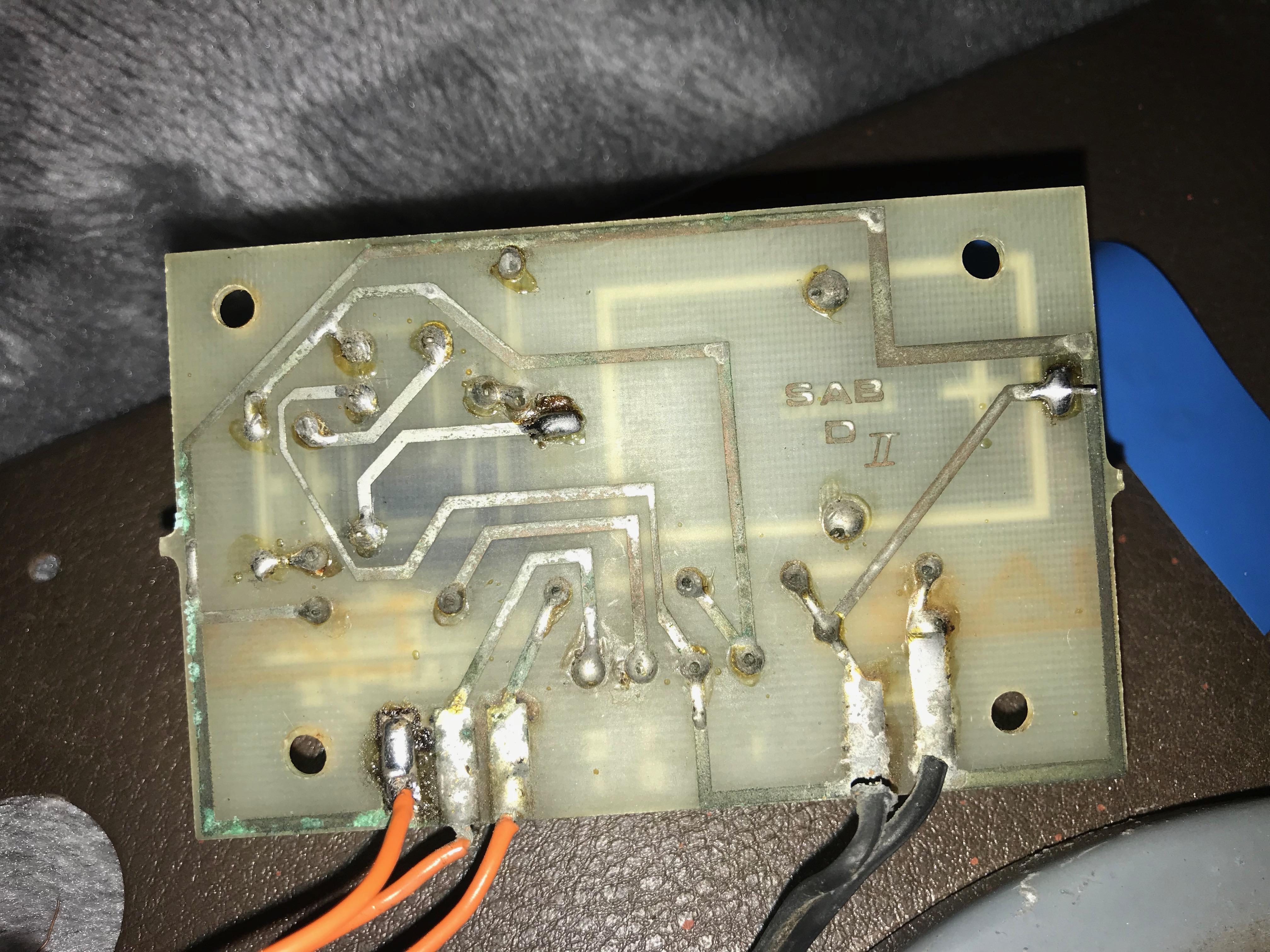
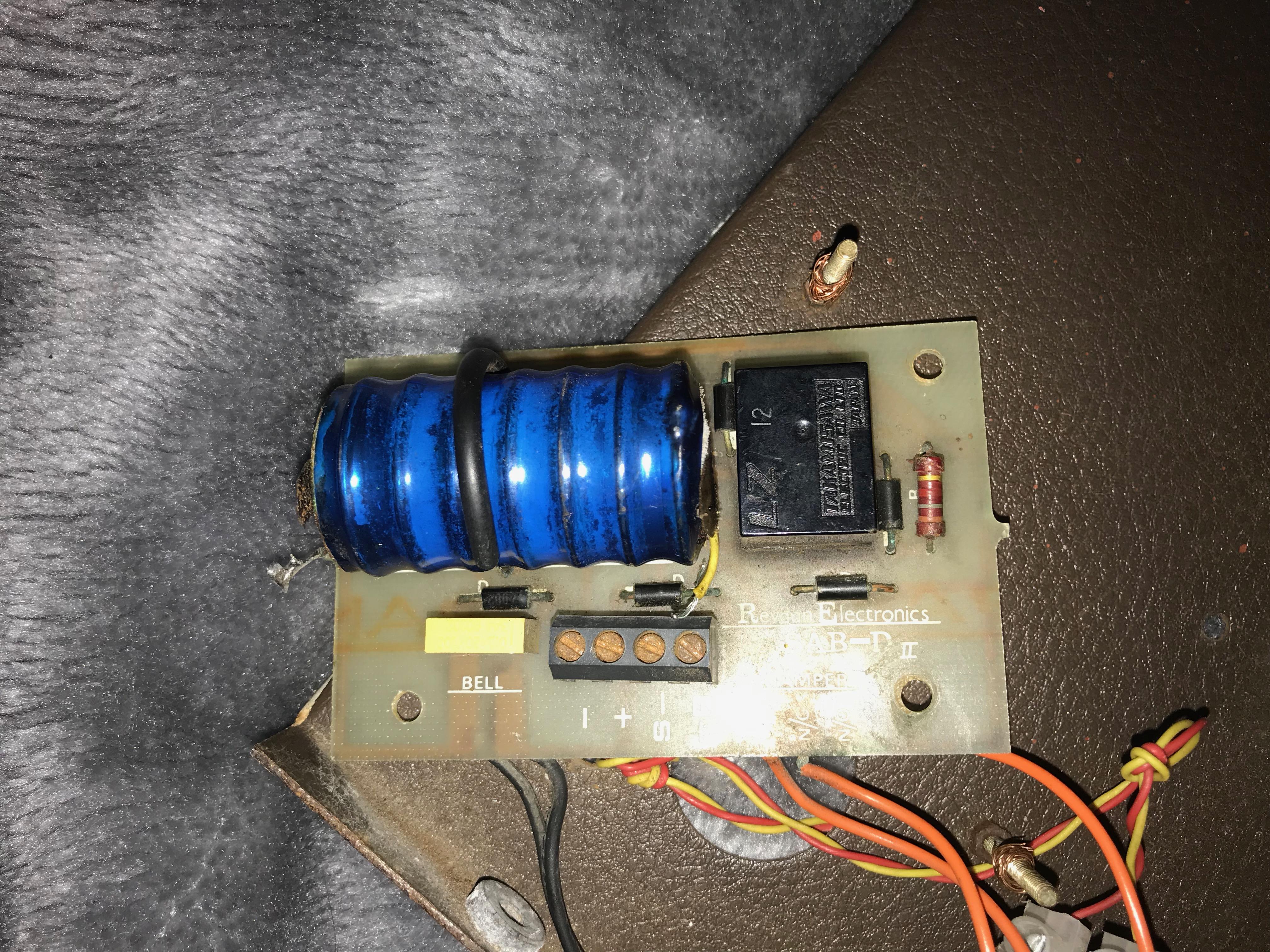

SAB Module
in Members Lounge (Public)
Posted
I will take that into consideration, those cells are much safer than lithium ones, but I'm surprised at how little there is in the way of circuitry on the board of the SAB I have, is the battery constantly charged until needed? I have ordered the relay I will be using for my circuit