_2d2230.png)
_5a42ce.png)

RevolvingSteve
Member
-
Joined
-
Last visited
Everything posted by RevolvingSteve
-
Cheers. So upstairs PIR are still set to intruder for function, but excluded from night set?
-
Arghh I removed the door contact and can't remember how I wired it as it only has black/red wire. I think this was just across the zone number and 0v as they don't need 12v?
-
Great advice. Thanks! I'll leave one of the upstairs PIR off for now and order the RIO.
-
Yes it is, I just don't have the expander to hand so was trying to get it finished today, didn't see a major issue with putting 2x onto 1 zone as they are just 'upstairs' and the manual states it supports unto 10 devices per zone, so I can't be the only person wanting to do this? I am the one with no knowledge here though, so if there is a good reason why this should not be done, just say, its all learning for me! Steve
-
11 x PIR'2, 2 x Door Contacts My other option is just to leave the other (Non Final) door contact for now and replace with a Wireless one...
-
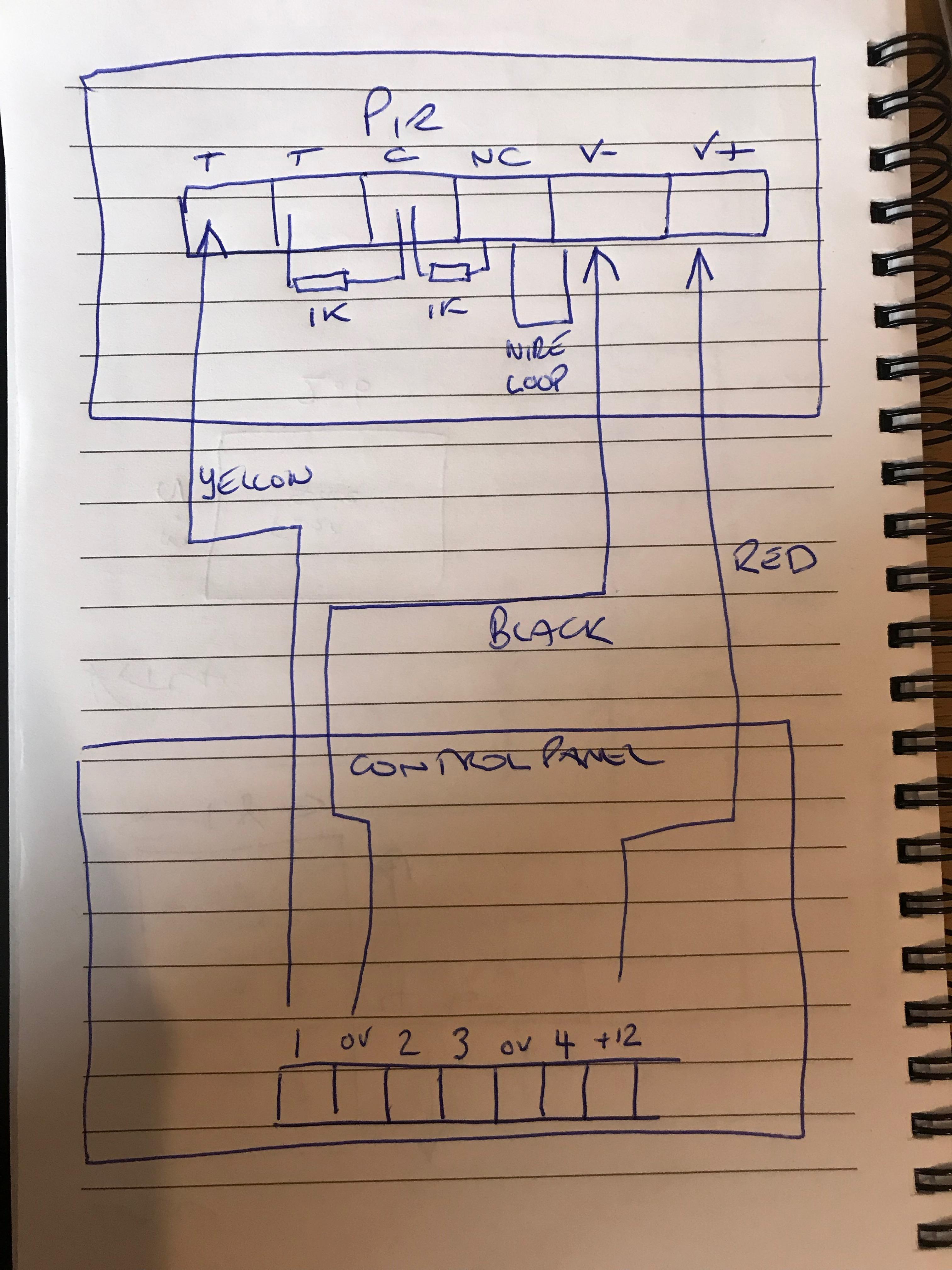
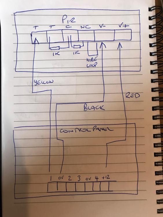
I am going to have to move 2 x PIR onto 1 zone (failed to take into account the final zone on its own door contact). TBH I almost put both upstairs PIR's onto 1 zone to start with so it was easier to omit/exclude them from the night arming, so I'm not bothered about now putting them onto 1 zone. How would I adjust the wiring on zone 11 & 12 given to compile them onto 11, I have the PIR's internally wired like the image below. Obviously replace '1' 0v '2' with 11 & 12!
-
Cheers. So I have configured the exit route PIR as 'exit' and the exit route door as 'final'. What's confusing me is that the hall PIR will be the exit for night set, and the landing PIR will be omitted from night set, what function do I sign the hall PIR? PRT ENTRY OR PRT FINAL?
-
Many thanks. Just renaming them all now.. slow! Maybe I should configure the Ethernet first and then I can do this from my PC? Doesn't seem to be a USB port as stated in one of the manuals
-
Question. I have not wired the back door sensor to zone 1 (final), it's easy to swap but does it matter? Looks like I can program edit and final function in the menu?
-
200 page manual it is then!
-
After some great advice on this thread: I now have the unit wired up, turned on, all faults cleared and the unit powered on with the time and date set, not much to others I'm sure but a minor milestone to me! :0) Finally got a day without work/kids/life steamrolling over any free time so going to try and get the configuration done today. En game is: 2 'Set' options (one for everything active when we are out if the house, one for downstairs when we are in bed) 3 Users created 3 Keyprox Tags assigned to the users Change passcodes for Standard 'User' and 'Engineer' users Ethernet module configured to access internet, DDNS setup, iOS App connected (Both Internally and Externally from the house) Is there a recommended flow of doing this or does it not matter? Any tips are gratefully received as always as the install manual is about 200 pages long! To add, is there a full menu map anywhere I can print off?
-
I have now cleared all the faults (the external sounder was my sausage fingers in the end). Today is configuration day.. God help me Im going to start a separate thread as suggested.
-
OK that's very useful information. It looks as though the resistance value in menu 51 ent 46 ent applies to all zones (although I only had a quick look). I think its probably just easier to buy the correct Honeywell Resistance version as they were only about £8! So I guess the same applies to the 2 x Bell housings (my other tamper issue, these are wired in series as per the instructions from the Manufacturer), but Ive not worked out where to put the 1k resistor yet. From your comment I should put it in the furthest BH on the tamper circuit return? Many thanks for the help, I provide a lot of advice on a AF Forum, but feel like a school kid when it comes to alarms! Good community.
-
Im just about to sort this, however, I have 2 doors on the same circuit (its the same room), so do I still use 2k2? Or will it double/halve if there are 2 x 2k2 on the circuit?
-
FROM MANUAL: <<<>>> Zone configuration The default zone configuration is 1 kΩ double-balanced with fault monitoring via a 3 kΩ resistor (preset 11). In the following configuration a mask condition is generated if an alarm and fault are signalled at the same time. If required, reprogram zone configurations and the resistance preset values using the Zone Resistance menu (51 ent 46 ent). <<<>>> So looks like it can be done! I'll test it tomorrow
-
If that's possible? I'll have to consult the manual.... The drawing is mine, but that's fine for the PIR's, this is for door contacts with resistors moulded into the unit so I cant get to them.
-
Looking at this page: https://www.cqr.co.uk/images/stories/cqr_pdf/Magnetic Contacts/Surface Contacts.pdf Looks like I've ordered the wrong one! They are pre-wired but Ive got type B: Type B Resistor (For Scantronic, Cooper, Pyronix PCX, Texecom, Castle-Care Tec G3+) [SC513/WH/G3/B] - 4k7 Ohm Switch, 2k2 Ohm Tamper I need Type A: Type A Resistor (For Honeywell, Microtech (Galaxy) - 1k Ohm Switch, 1k Ohm Tamper Rookie error I think!
-
Yep, maybe I just bought the wrong ones! Ive just checked and here: https://www.securitywarehouse.co.uk/catalog/intruder-alarm-c-36/door-contacts-switches-c-36_44/cqr-grade-3-white-surface-door-contact-with-magnetic-detection-p-4714.html It seems to imply they do have resistors? Am I just being thick?
-
Right, after 3 weeks of Xmas madness I got back onto this today. Fired the alarm up and I have one fault which is 'Tamper O/C' on zone 12 (1018 from memory), which is the door contact for the back door. The issue I have is that the door contacts only have 2 wires (Black/Red) so they don't seem to have a tamper circuit or anywhere to fit a resistor? I presume this is done at the board, but should the resistor just be inline on the '12' terminal?
-
One of these: https://www.securitywarehouse.co.uk/catalog/intruder-alarm-c-36/security-control-panels-c-36_102/control-panels-all-c-36_102_41/honeywell-galaxy-dimension-boxed-rio-p-698.html ?
-
Im going to run out of PIR zones as there are only 12 on the board. 'Garage' for example I am happy to have both PIR on 1 zone. Thought that was OK, but please advise if Im being dumb!
-
If I need to wire 2 x PIR into 1 zone, do I do this in parallel?
-
Many thanks GalaxyGuy for the confirmation, appreciate your time, sure it won't be the last question!
-
Not sure exactly what that means, the terminals on the board go as per the diagram in the first post, instructions state 0v in between the zone terminals to be used for V- ?
-
Ok, so take the brown core for example into NC and pair it into 0v with the yellow at the board?