

Eugene's DIY Den
-
Posts
118 -
Joined
-
Last visited
-
Days Won
1
Content Type
Profiles
Forums
Events
Downloads
Gallery
Blogs
Posts posted by Eugene's DIY Den
-
-
Replaced all the contacts two months ago in the same position. Haven't had any issues with false alarms.
-
9 minutes ago, MrHappy said:
If the gap is too wide the reed may not close / may open after a period of being set
Depending on the case design you mage be able to double up the magnets which give them more "pull"
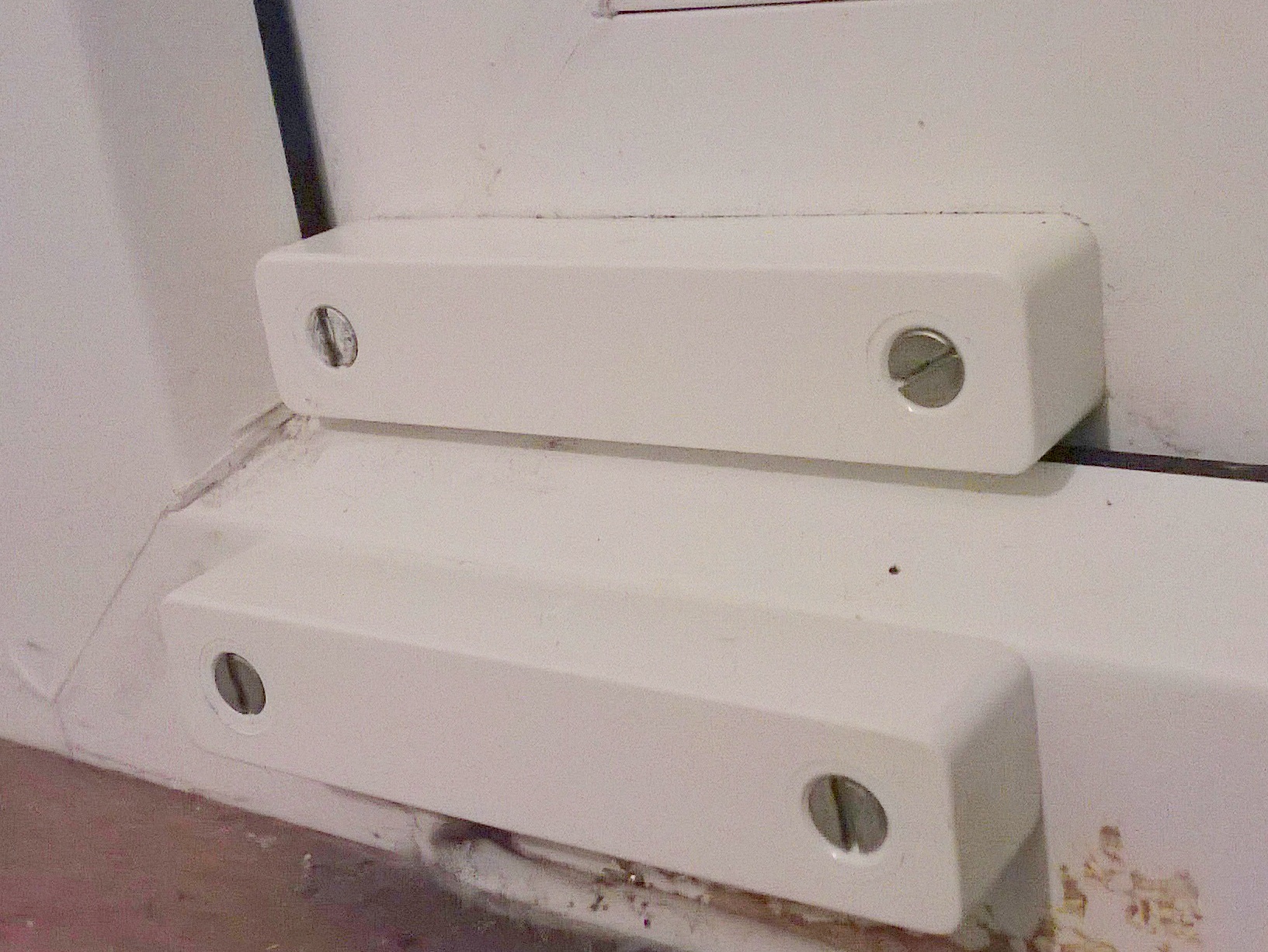
I could probably piggy-back the magnets and use long screws. I would prefer to keep the contacts off the chamfer if possible, plus the wiring would have to be stretched (mightn't be possible) , plus holes where the contacts were, left visible in the window. About 22 pairs are like this.
-
6 minutes ago, MrHappy said:
there on surfaces which are stepped apart, a "chunky contact" does 30-40mm gap I wouldn't fit then in the locations you've got
What would be the consequences of spacing the pair this far apart?
-
52 minutes ago, MrHappy said:
IIRC 13mm operating gap, thats look way too far apart
The bottom edge of the magnet to the closest edge of the contact is 11mm.
-
1 minute ago, MrHappy said:
The reed is just little bit of metal in glass tube....
I reckon most of the branded alarm contact manufactures buy in the same Reeds...
The gases escapes for the glass tube & they either FA or just fail (open or closed)
I suspect those the fail early have been thrown around or the screws knocked in with a hammer when fitted
I fitted the contacts, so there was TLC involved! However they seemed to fail after a few years on the windows which weren't opened. The currents involved are only milliamps, so they hardly weld closed?
-
Two more questions!
Do magnets lose their strength over the years. I tested a new contact I replaced with both the old and new magnet. Both contacts opened when the magnet on the window moved outwards 1 cm. It's probably good practice to replace both contact and magnet?
Second question:
The PVC windows have a chamfered edge, so I can't butt the contact up against the magnet because it would be proud of the window opening and likely to get knocked if anything is passed through the window. At the moment, the contact only opens when the casement is pushed out 1 cm. Tapping the contact hard doesn't seem to open it when the window is closed, so the reed switch seems to be securely closed. Do you think this is good enough, or am I going to have problems down the line with nuisance triggering because the pair aren't close enough?

-
So a lot of my contacts need to be replaced, most of them on windows which are never really opened. A few are on doors and windows which are regularly opened. The switches are sticking closed.
Is this typical if the reed switches aren't "exercised"?, or did I just get low standard switches when I installed my alarm almost 20 years ago? -
On 8/11/2017 at 10:11, al-yeti said:
White leds show up good in the day though...
At night time, the LEDs are quite good. Not sure whether brightness increases when in alarm state though?
-
Sounder now on wall and working fine. Pity the strobe on the HKC sounder (3 so called 'high intensity" LEDs) is so crappy. The xenon tube on my old sounder was much more effective. Maybe it'll be better when it's dark.
Thanks for the help everyone! -
Ok, I think I'm beginning to make sense of these EOL resistors. I'm guessing the EOL resistor is the bottom resistor of a potential divider, the other resistor is in the control panel. The panel detects 0volts, high volts 5v? and a reduced voltage, Possibly half voltage when everything is ok?
So there are three scenarios:
1) Zone wiring is shorted by burglar or fault, producing 0 volts at the panel2) Wiring goes oc due to a sensor being triggered, a cut wire, loose connection or whatever. This produces a high voltage at panel
3) Normal conditions - EOL resistor plus series resistance of loop. Panel detects an intermediate voltage.
On my SCB, when its tamper switch is closed, the transistor is on, pulling the EOL resistor down to ground. When the tamper switch operates, the transistor opens and the end of the resistor floats so it's taken out of circuit.
-
4 hours ago, james.wilson said:
no in this case it allows the panel to detect if the wire is attacked and someone tries to defeat the sab tamper by shorting to 0v. You need a panel that supports this feature
On my new sounder, if tamper return from the panel is connected to NC, the bottom of the 4.7k resistor (attached externally to the terminals) is either grounded when the transistor is on, or floating when it's off, depending on the state of the tamper switch in the sounder. So the resistor is either connected in parallel with the tamper lines, not connected, or the third state is someone has defeated the tamper by puling the line to 0v. Is 4.7k (or whatever resistance) the normal resistance for no alarm to occur, and then either a short between lines or the resistor floating with the transistor off, the two conditions which trigger an alarm? -
9 hours ago, james.wilson said:
as already mentioned you only use the nc connection if using the sol resistor. In this case connect to tr (tamper return)
Ok, so the resistor value allows the panel to identify which device generated a tamper?
My panel has two pairs of tamper terminals: '24 hr' and 'SCB'. Are these typically looped in series within the panel on the PCB? So the SCB terminals are just for convenience so that the tamper loop for sensors doesn't have to be broken to add in the SCB tamper circuit. -
15 minutes ago, al-yeti said:
Have you done it and what's the issue ?
No, not yet, don't want to damage the sounder and/or panel if the connections are incorrect. Probably damage is unlikely because voltage supplies are produced by 7812 and 7805 regs which are short circuited protected, but just want to be sure.
-
25 minutes ago, sixwheeledbeast said:
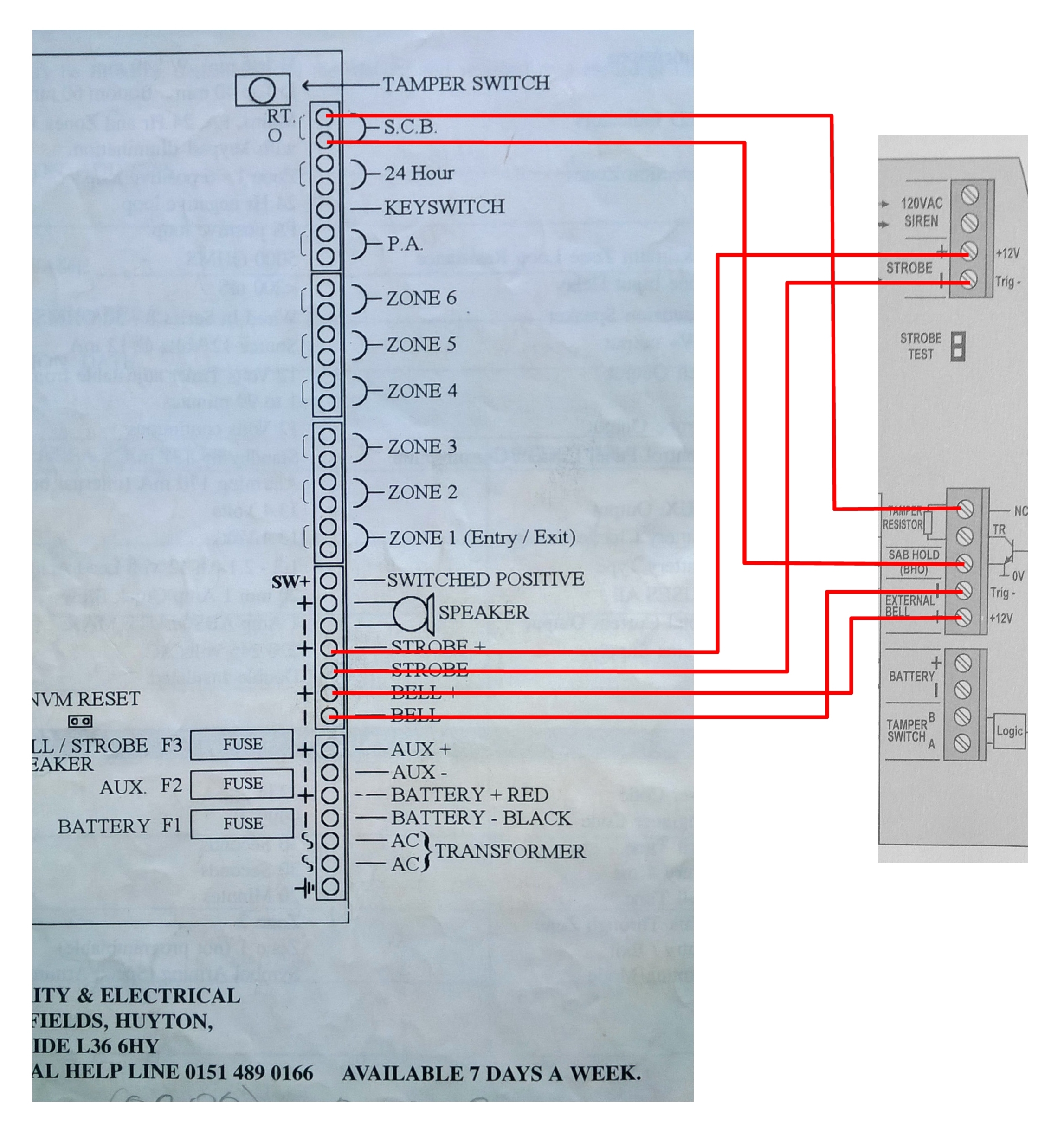
I'd say all looks correct but the SCB return should be in TR not NC (which I assume from the diagram to mean "No Connection" and not "Normally Closed")
As for the electronics behind the panel I have never seen the panel so difficult to comment. What you have said seems right for panels of that era tho.
Yes, I would have thought that and pull up to 5v is at the point where NC is marked on the sounder. Then tamper return monitors voltage on the collector of the transistor which goes high or low depending on how the logic is setup.
This photo (sorry about the quality) shows how they recommend connecting another panel. It seems to show tamper return connecting to the top screw terminal in the block, rather than the next one down. Maybe it's an error. I'll contact them tomorrow
-
Can't seem to edit original post (is this not possible once a period of time has elapsed?). Panel is a ZX6, not an SX6.
-
Ok, so I'm a bit confused about how the internal circuitry works for zone o/ps, switched negative o/ps and tamper o/ps. Terminology and o/p descriptions vary a bit on different panels and sounders, so I'm trying to get my head around it.
1) Bell/strobe switched negative - Is this o/p on a panel just an open collector transistor whose collector is pulled low when the base is driven, providing a ground for the strobe and sounder?
2) Zone inputs - Is one leg of the input connected high via a pull up resistor to the 5v supply, and the other leg tied to ground? When contacts are closed, voltage i/p is pulled low, then goes high when a contact opens
3) SCB0 and tamper return - Is SCB0 a permanent, nonn-switched 0 volt supply for powering a sounder? On some panels this is hard wired to tamper feed which is sort of a misnomer because it's a feed of 0 volts, rather than positive voltage.. Is tamper return a 5 volt o/p pulled high by a resistor internally or a fixed 5 volt supply?
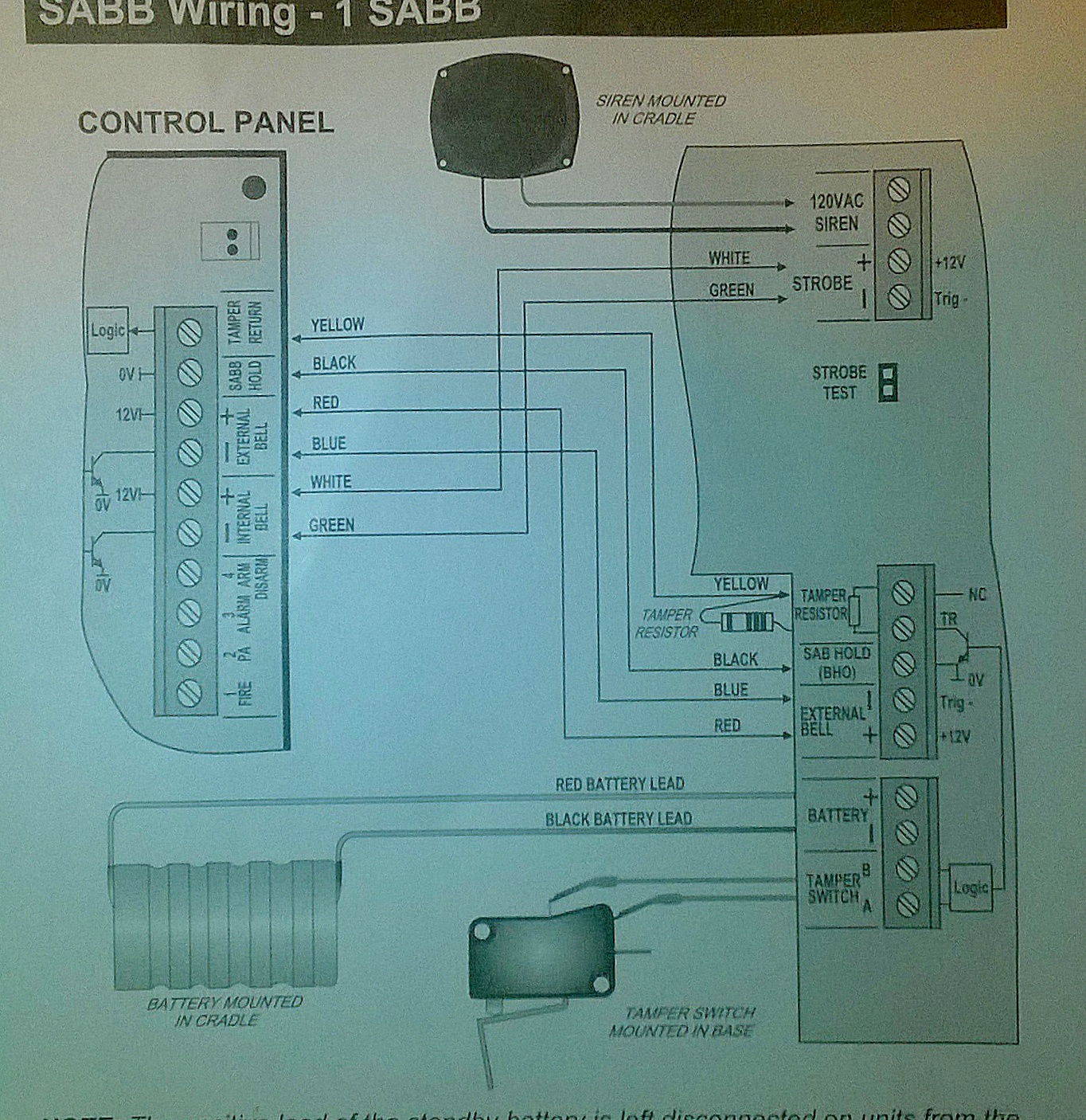
I'm trying to wire up an old A1 security and Electrical Advantage SX6 panel to a new HKC SABB sounder. This is the way I think the connections should be made.
"Keypad Engnr" message on Abacus LCD Alarm Panel
in !!..DIY Installers..!!
Posted
Someone has asked me whether they can resolve this problem on their alarm themselves and what could be causing it. When they set their alarm, after around a minute, the alarm sounds and the the log shows the reason for the alarm to trigger as "KP1 Engnr".