_2d2230.png)
_5a42ce.png)

Gabs
Member
-
Joined
-
Last visited
Everything posted by Gabs
-
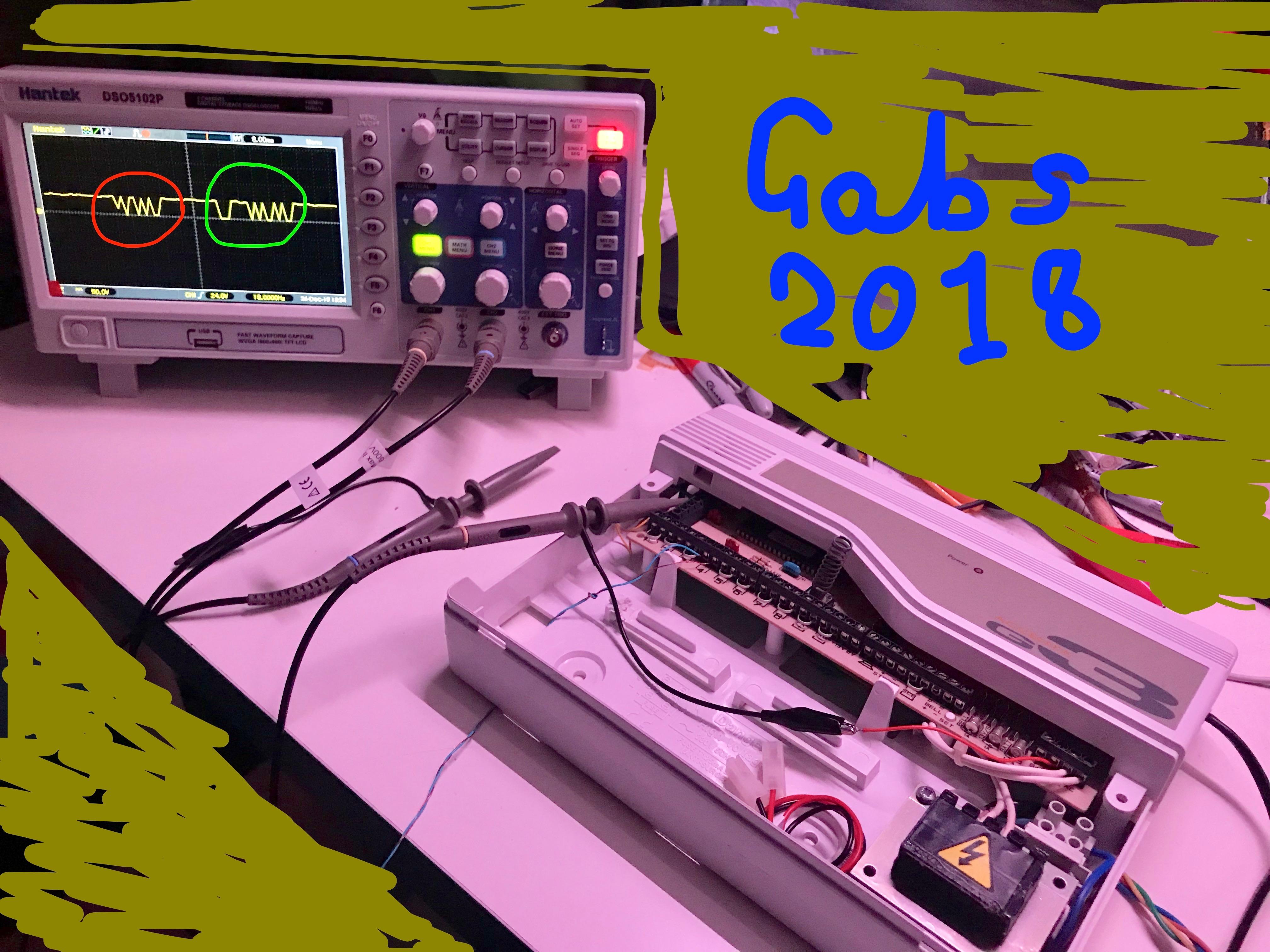
ANY HELP IS GREATLY APPRECIATED Would anyone be able to help me in finding out how a keypad talks to the main panel, I have an oscilloscope asd I have connected it to the 'Comms' wire, when the Accenta keypad is connected to the panel. This wire is at a constant 5 volts, with dips in this voltage when a button is pressed, or the panel needs to send the keypad information. This first image shows the data line between the panel and keypad when 1 has been pressed, these dips in the 5 volt signal were created by the keypad, for the panel to recognise. The above image shows what happens when the 'PROG' key is pressed. The highlighted in red waveform is the keypad sending the Prog signal to the panel, the one in green is the panel responding to the keypad telling it to light up all LEDs. What I do not understand is how the keypad can create a dip in the 5v line if the panel is constantly giving out 5v, same with the panel, how can it then create a drop in the voltage in the data line, if the keypad is constantly giving out 5v. The only way I thought it could be done was the panel shorts out the keypads data line, and the same with the keypad, it shorts out the 5v of the keypad to create 0v in the 2 way data line. Just wondering if this is correct? If anyone knows. I have tried the sound line, however it doesn't carry any data, just 'beeps' and alarm tones.


-
Shame it is out of stock. Looks quite advanced for one. I will just have to try trial and error for my design, I have one, but it would only be one time use, as it wouldn't be charged up again
-
Might have been, taken any of them down recently? I would try to design the circuit like that, just don't want to damage my panel, if it goes wrong. I have built a few Security-Related circuits recently, Don't know anywhere that would sell old stock SABs

-
I will just do that, then. I can solder one straight to the board. The dilemma still lies in the battery charging circuit, I think a 1 watt resistor would do, constantly powering the battery until it is needed, that is why ideally I have an SAB module to copy the circuit from, and understand how it would be charged. Was going to see if I could get it to work with this, once I have built it http://www.zen22142.zen.co.uk/ronj/sh.html
-
The idea was just for a microswitch to go straight to to SCB of my Accenta panel, I could route it through my SAB module, but it would just be two tracks, from one terminal block to another. Could be done with standard 6 core wire, too. 2 for the Tamper 2 for the Hold Off voltage 2 for the Siren
-
I was going to do that, butt thought it would be a little easier to use the + and -, I could keep everything positively charged inc the siren, and then I would be able to make it a neg trigger, but since I have terminal block in sets of 2, the full on + and - should do, just use an extra core. I remember that, it works with the panel, which I still have. It is good, for an early panel, all hand-etched boards in it
-
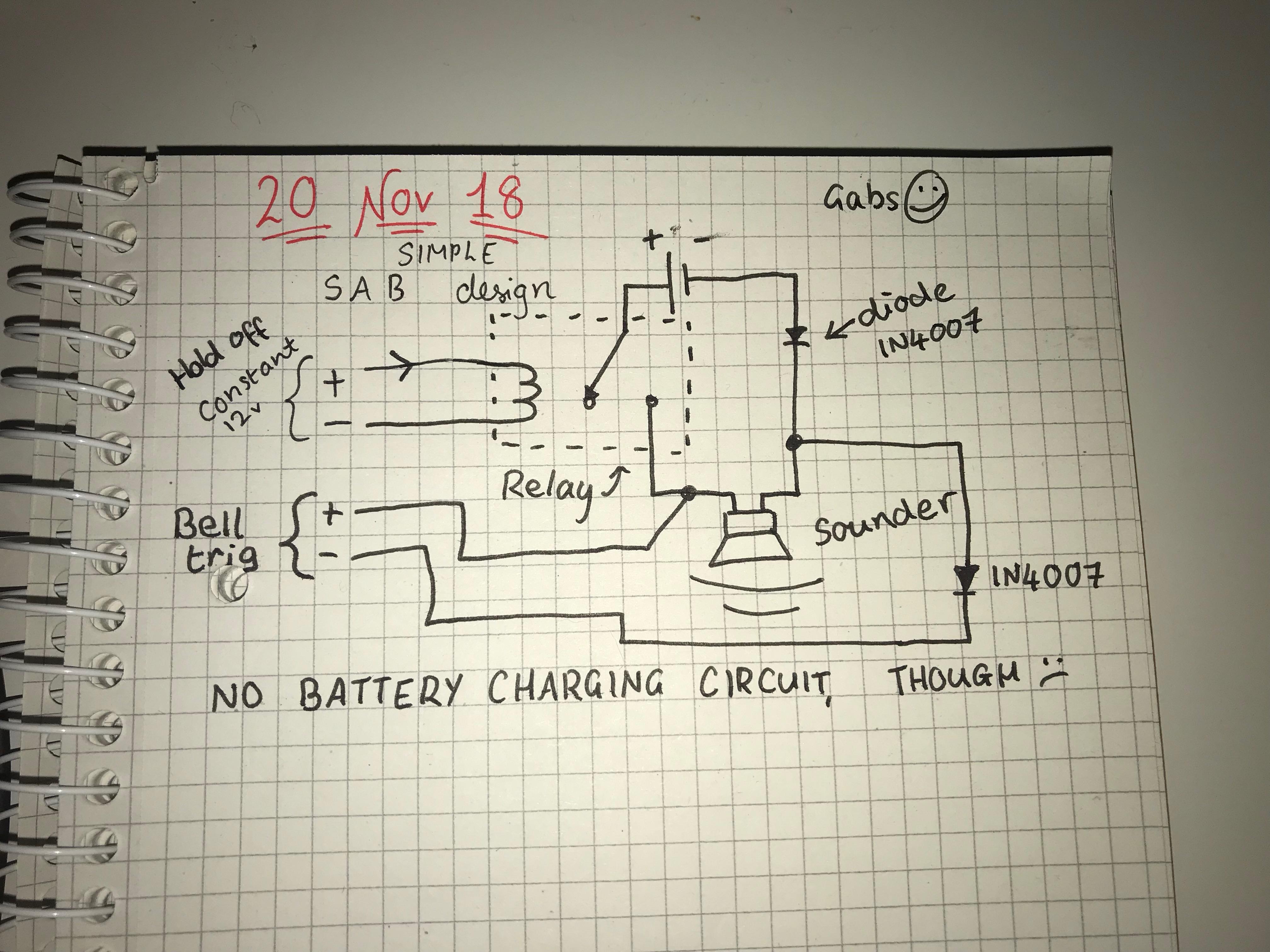
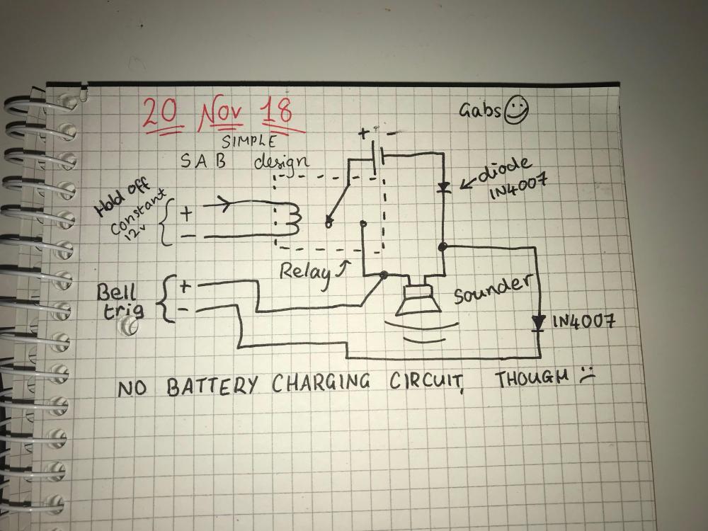
Think I have cracked the part without the battery charging circuit, really quite simple
-
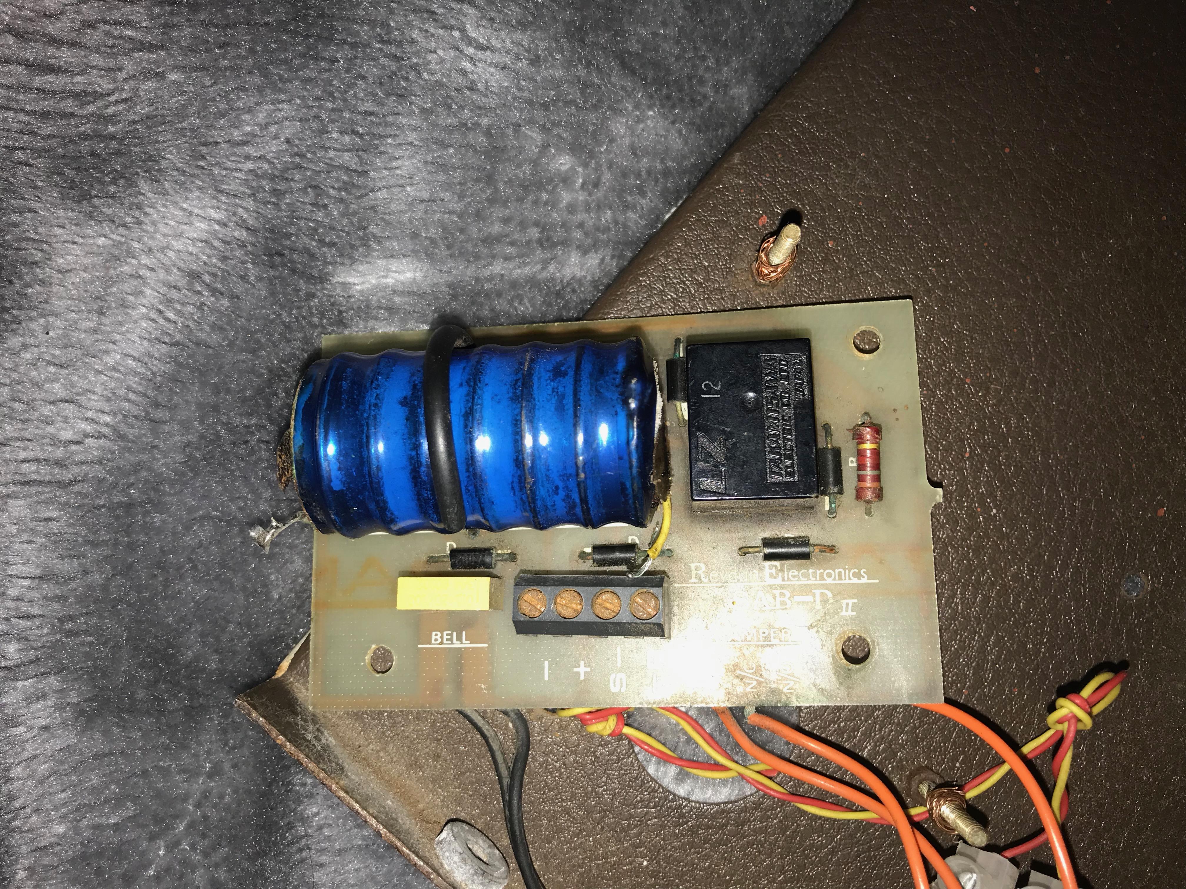
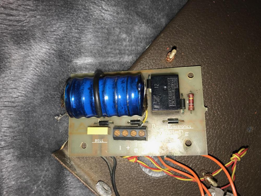
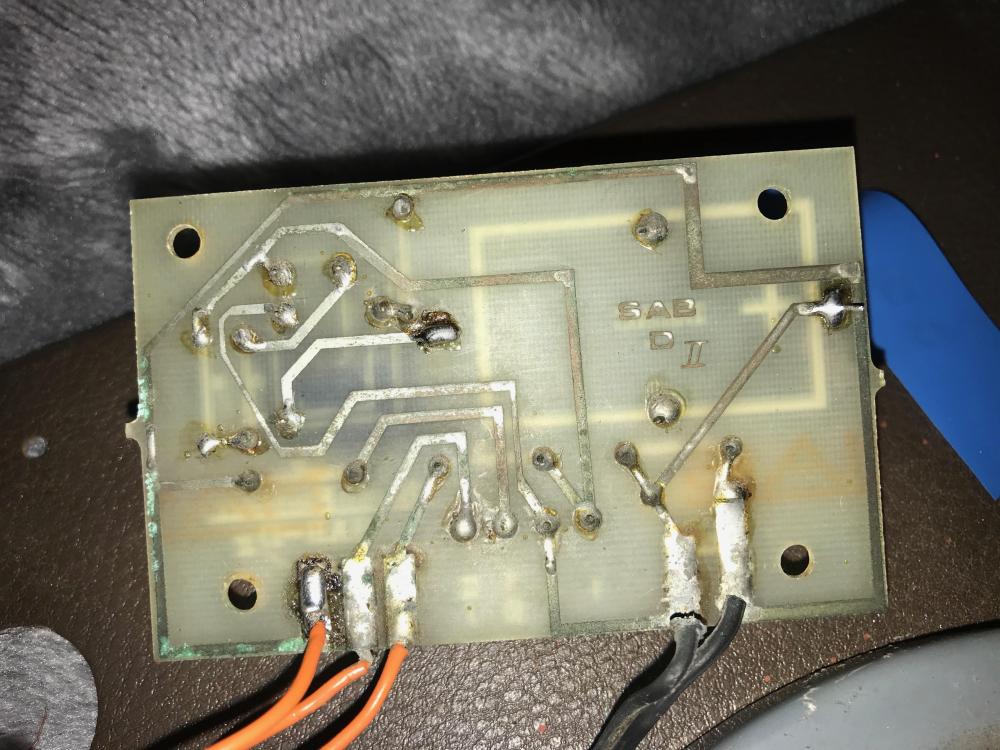
Yeah, that is correct, the negative of the battery goes into the relay. It would be very easy to make a bell module with no charging circuit, you'd only need a relay. Board looks hand-etched too. And it could be SCB, it is powering a bell, not an electronic siren, so I can't imagine that battery lasting long anyway. It amazingly still holds a charge.
-
I will take that into consideration, those cells are much safer than lithium ones, but I'm surprised at how little there is in the way of circuitry on the board of the SAB I have, is the battery constantly charged until needed? I have ordered the relay I will be using for my circuit
-
-
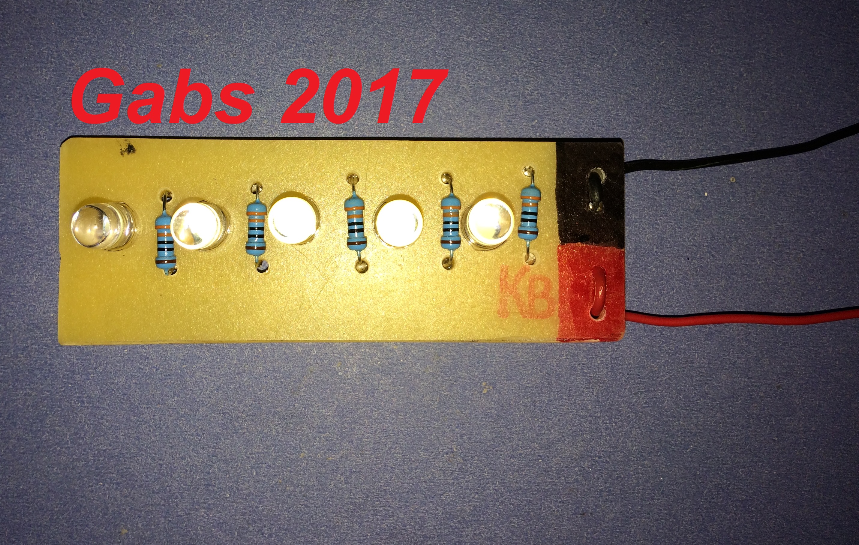
got these two photos of a very old one I have, but its not brilliant, that's why I'm setting myself the challenge to design and make a new one
-
Thanks for the reply. I actually used a CMOS 4001 chip, and it worked pretty well. I was thinking of using a betray like this: https://uk.rs-online.com/web/p/coin-button-rechargeable-batteries/0525815/ bit safer than a Lithium one. Thanks, I'd appreciate that, I have a basic circuit design, just not sure of it at the moment.
-
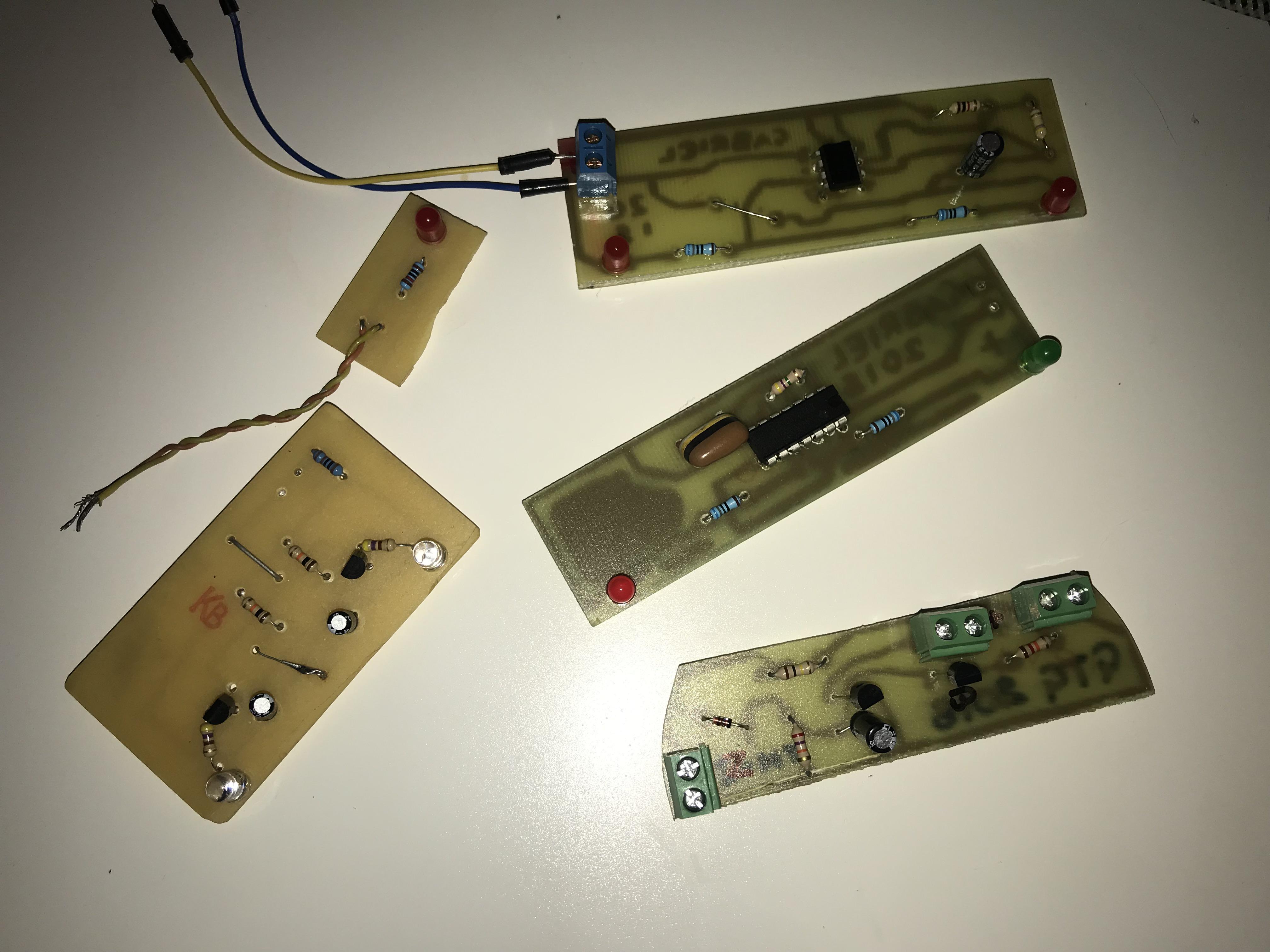
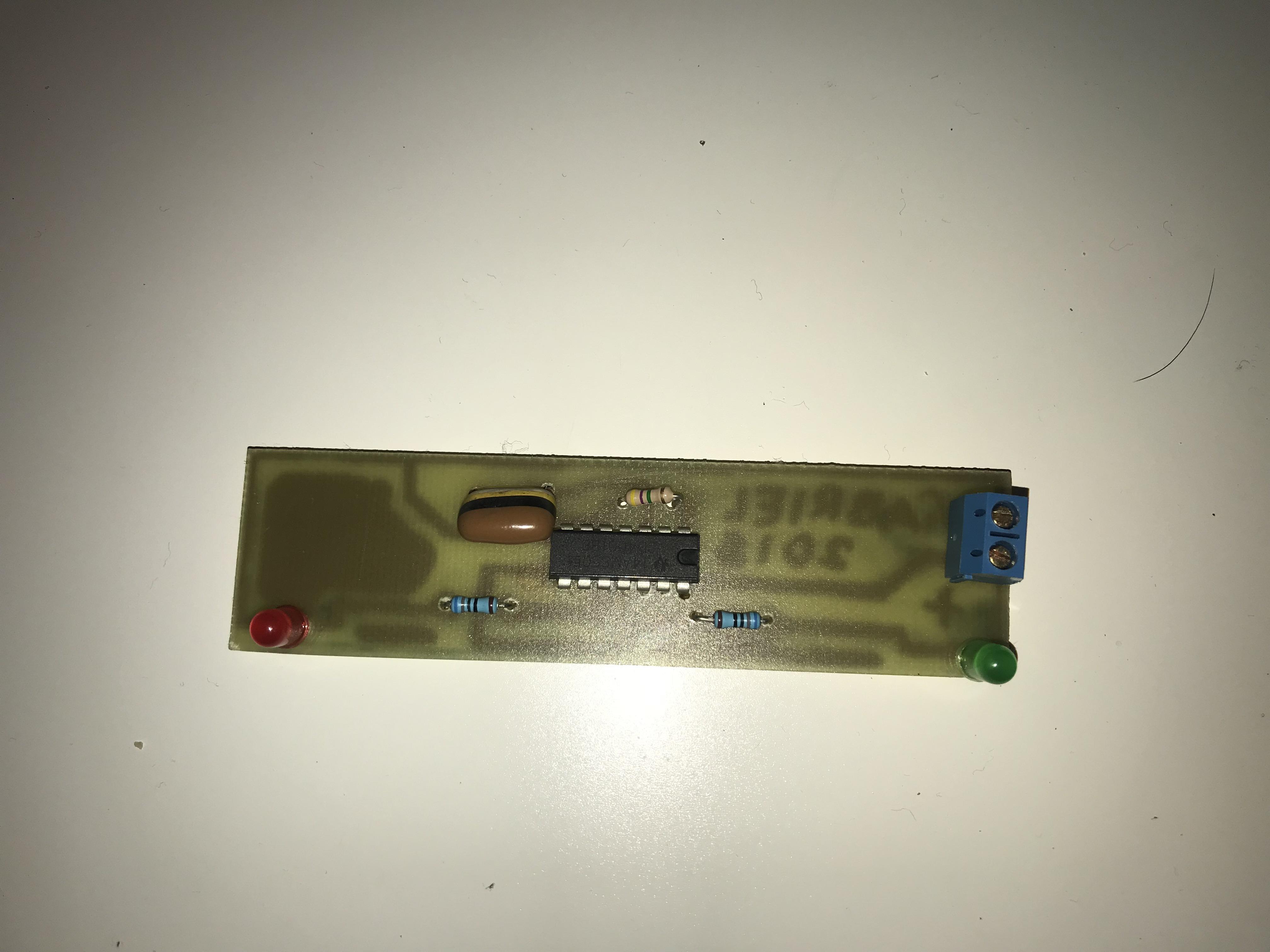
Some time ago, I was directed to this site http://www.zen22142.zen.co.uk/ronj/shs.html when asking about an alarm panel schematic, I am in the process of building a panel from this website, however, I was wondering if anyone had a schematic I can use to make an SAB module, or bell module, or even if they have one would be able to get a photo of its PCB tracks, and components, so I could have a go at tracing them back out. I have an idea for a circuit, its the Ni-Cd battery charging bit I'm unsure of, any help would be much appreciated. I have included a photo of a CMOS LED flasher I made, this could be the comfort LEDs of the bell box, Gabs

-
Sounds very reminiscent of my school, that I have just left. I took product design as a GCSE, but was never given the task to do anything as exciting as make my own alarm panel. Do you have any pictures of the alarm panel that you made? I'd be interested to see Sounds like a funny thing to do, although it would ruin the books
-
That's good I have decided that I will probably build one of the transistor panels from Ron's site, so the components will help me there, thanks Yeah, it is. Shame Velleman don't make alarm kits, they mainly do things to do with lighting, so not as good.
-
Thanks, I'll have a look at that, schematic looks pretty big though, more complex than the Logic 4
-
What bits and pieces do you have? Old components, panels? Or just a mixture of things? Just curious, before I go off to Maplin and buy some Transistors for a Circuit on Ron's site
-
That's bad that you were accused of buying it, but it also says it was better than anything the teacher was expecting. With old parts, if I make my own panel, I'll have a go at vacuum forming a casing for it, would be rather rewarding to do, making the panel from scratch.
-
Yeah, would weigh much less. Have you ever tried making your own alarm panel?
-
Yeah, the metal ones seemed to offer much greater security than the plastic ones. Although the plastic ones look nicer, well, as nice as a black and white plastic box can look. Think white is the best colour for a panel
-
Cheaper than the Accentas then. I can see why it cost that, I guess a lot of thinking and design went in to it. Thanks, that'd be great. I always have this tab open, so I'll just check my PM every now and again. Thanks, I have always been interested in this sort of stuff, I was thinking of building something like this http://www.bentleysecurity.com/ that my be more simple.
-
Wow, thanks for the replies guys I will look on his site, I actually have been using and learning with my Arduino Microcontroller, in this picture, it is connected to my Accenta G3, I made a Mission Impossible stile beam break detector hooked up to Zone 4, so an instant alarm when set. I will have a go at some projects from his site tomorrow before I take on the Logic 4, which was probably designed by an engineer with a lot more experience than 16 year old me I have built sme things, I etch my own PCBs as well, to put my very small projects on. I'll also add a picture of a PCB that I have made, it was designed to be an LED version of a Airbus A320 wing strobe Ah, the microprocessor stuff does sound much more complex, I'll stick to the basic ICs for now And let my knowledge rise first. I actually have a kit similar to the Tandy one, it was my Dad's he gave to me at quite a young age, before I started messing on with proper alarm panels. I have an Arduino microcontroller, which I made wok with my ADE simple set reader, which as fun, thy worked together really well, making the Arduino control a siren, depending on the relay state of the set reader. I know, I would be quite interested actually o see how the Logic 4 and Optimas were designed, the PCBs have quite clearly been designed by a computer program, although I do not know of any PCB design programs existing back in the early 1990s. I have just ordered 50 555 timer chips, so hopefully I'll be able to design something good with them, and other chips I have. I guess they were designed with simplicity for the user in mind, that's what I like about ADE, nothing is ever too hard to do on their panels. How much was the Logic 4 at the time?


-
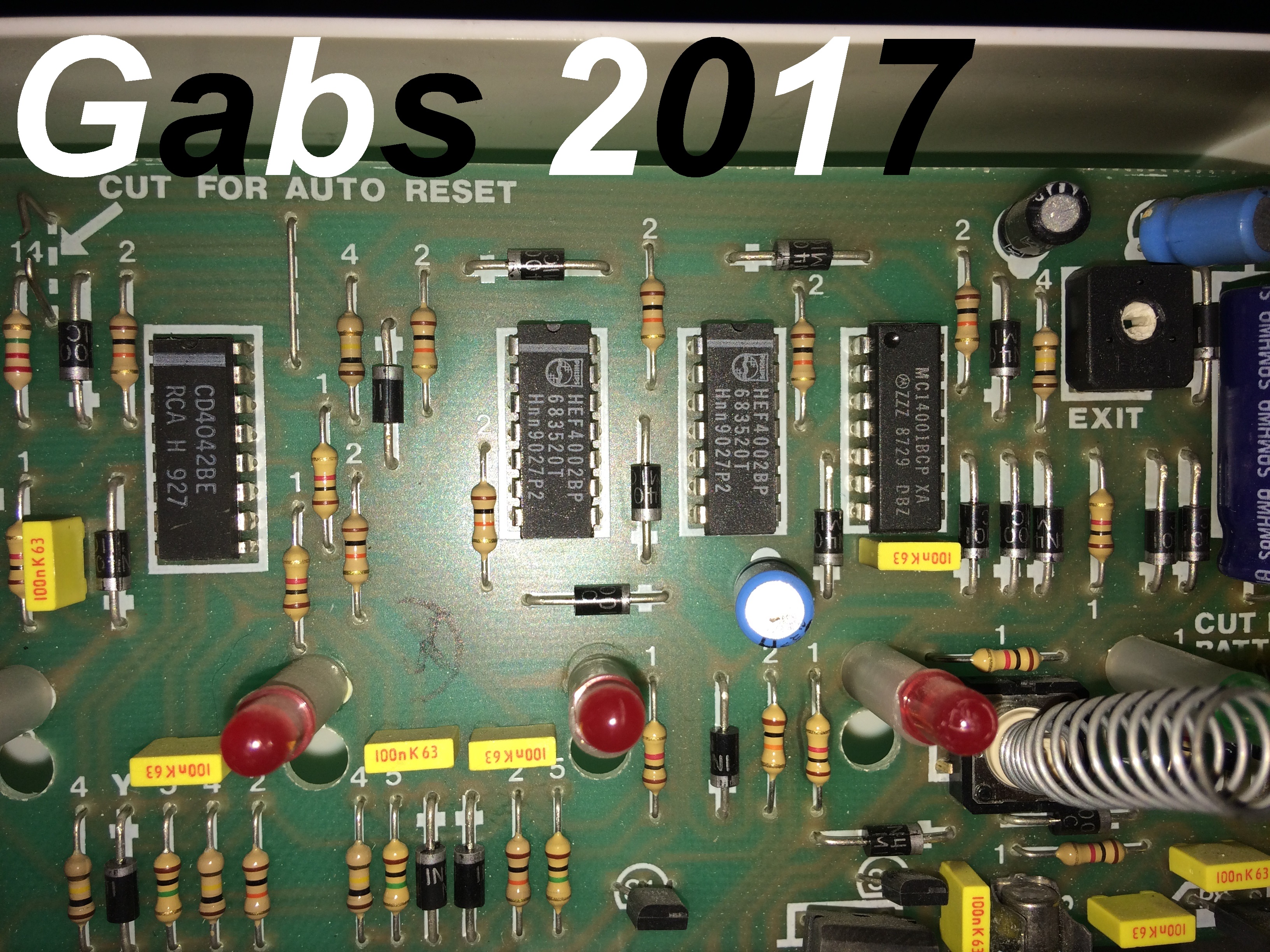
I actually have just got a Logic 4, it looks really quite complex, I could give it a go, but I am not sure if it would work. Here are the 4 ICs in the Logic 4, not sure if any are custom made for ADE, would anyone else know? If not, there is a chance I will try to make/copy the board traces for the Logic 4 I'll have a look at that, thanks

-
Thanks for the replies, I just thought using a micro-controller may have been easier than using more passive components, such as individual logic ICs. What sort of kit was it? I'd be interested to know, and maybe try to build one. The description part also sounds helpful
-
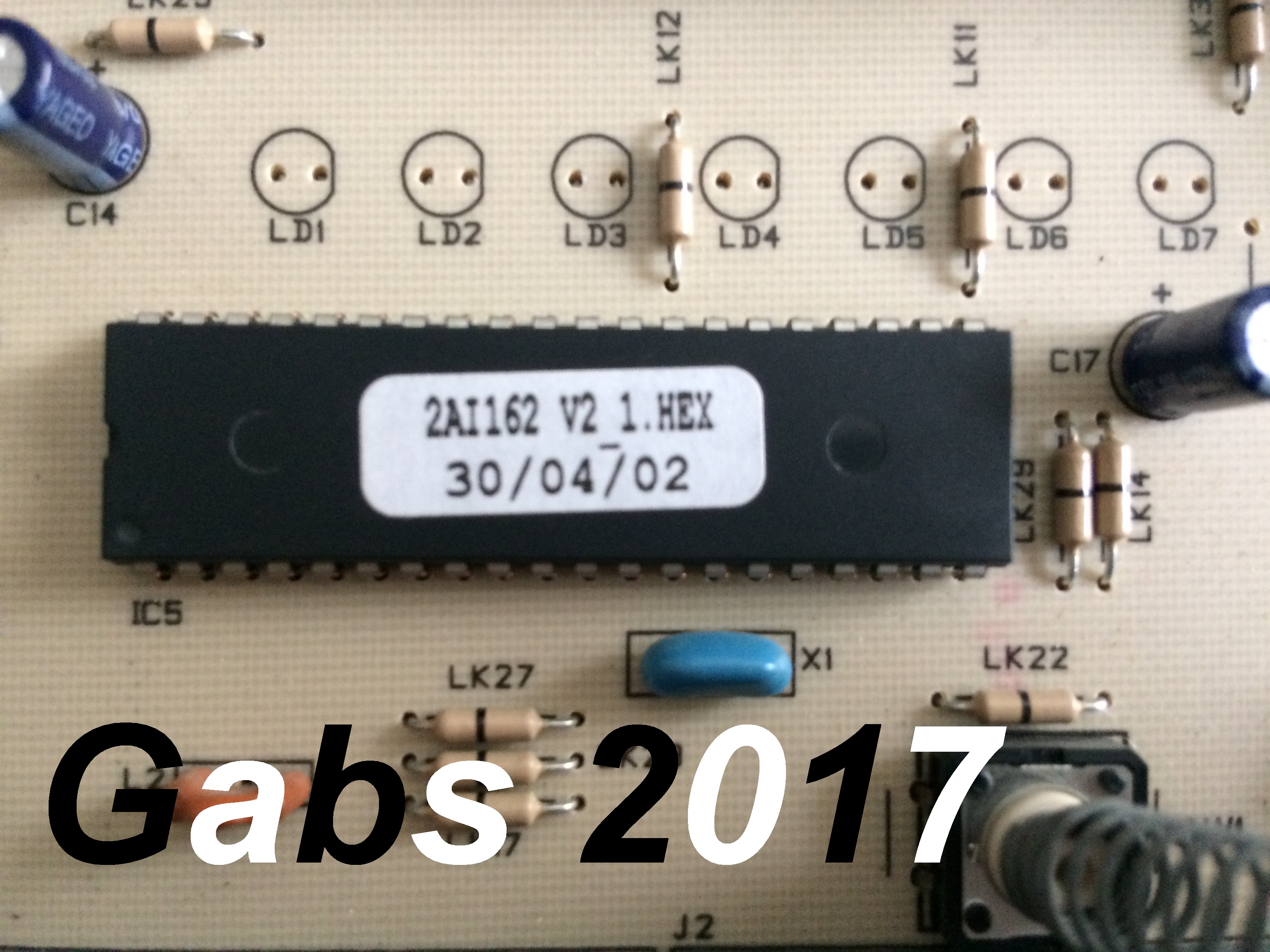
Does anyone have, or know where I can get a schematic for any alarm panel, (Preferably ADE), reason for me asking, I am very interested in engineering and how these panels were designed.I was thinking about making my own panel, using an ATMEL microprocessor, and a custom made PCB. I was mainly interested in seeing how the zones and inputs are connected to the main microprocessor of the control panel (Picture shows what I am assuming to be the PIC microcontroller of an Accenta G3) I'm also interested din the software that the alarm panels run as well, so if anyone knows a little about how they are programmed and what language is used, I'd really appreciate it Thanks In Advance