




Foldart
Newbie
-
Joined
-
Last visited
-
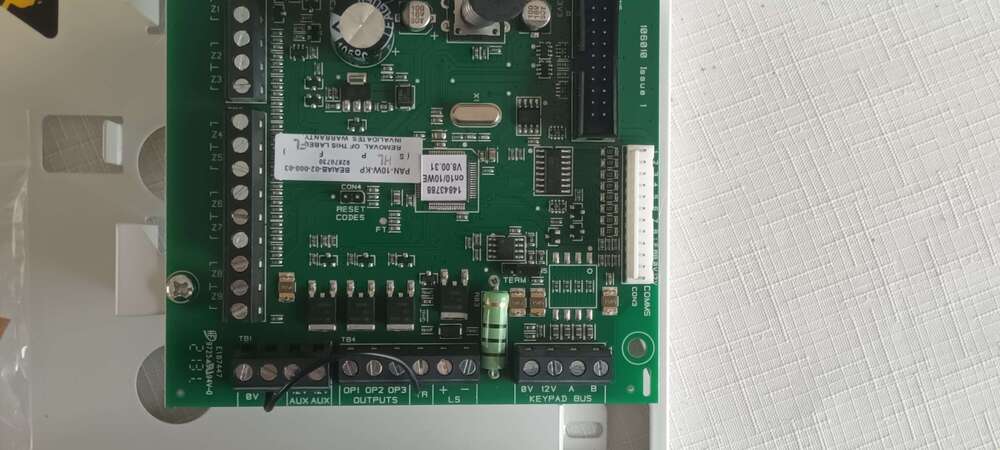
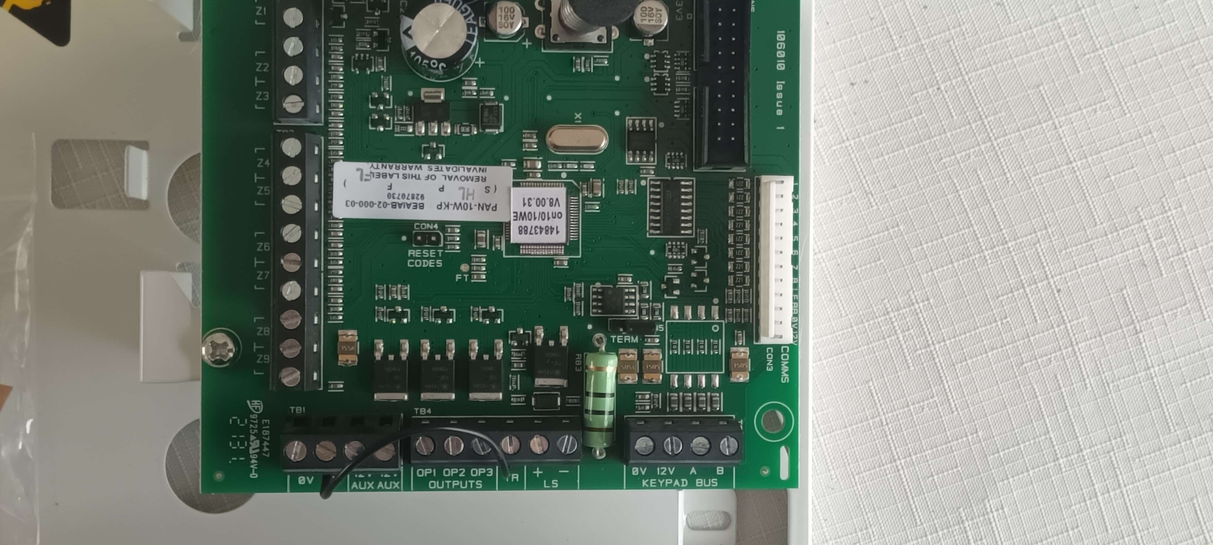
Hello. Apologies for the long message. Obviously technology changes and as I’ve been retired for a number of years it’s has changed. The Home Alarm system I fitted 20 plus years ago has finally given up so I have purchased an Eaton Scantronic PAN-10W-K Included with the Unit were QR codes to download User and Installer Manuals. While I was able to download the User Manual I was unable to download the installation Manual as I had to register my details and as I was not part of a company I was unable to do so. So this means I have a problem with some connections as the Main PCB connections are not obvious. The connections for the PIRs seem to be obvious with two zones sharing a common connector and a dedicated connector for each PIR. So I will wire the PIRs ( Without EOL resistors ) , no problem but I will not bother with the Tamper Wires unless someone thinks it’s a good Idea that I should. If I don’t connect Tamper there must be a wired link I should do so where / how. If I do connect the Tamper wires where do I connect on the Main PCB ( See Below ). I realise that he Tamper for the Keypad is done digitally. My problem / Confusion is connecting the External Sounder. The old Alarm showed connections as, -R Sounder Tamper Return ( Negative ) - Sounder Hold Off / Supply ( negative ) + Sounder Hold Off / Strobe ( Positive ) S Sounder Switched Negative Trigger ST Sounder Switched Negative Trigger There are Ten connections on the Eaton Scantronic PAN-10W-K. 0v , 0v , 12v Aux , 12v Aux , OP1 , OP2 , OP3 , TR , LB+ , LB- I suspect that one the 0v and 12v Aux can be used for the voltage to the PIRs but where / how do I connect he Sounder ?. While I have not connected / powered up the unit when I do I have to hold both the A button and Tick button at the same time. One of the options is 2 wire FSL but this also shows 2k2 / 4k7 which is for EOL resistors. As I won’t be using EOL resistors is this a problem or is there another setting ?. Many thanks in advance for help, advice and suggestions. Don.