

BveshPatel
-
Posts
27 -
Joined
-
Last visited
Content Type
Profiles
Forums
Events
Downloads
Gallery
Blogs
Posts posted by BveshPatel
-
-
There maybe a little bit of a confusion here. It's not multiple FSL but rather two contacts on a single zone is using FSL/EOL where the last contact has the 2k2 resistor in and the first contact only has a 4k7 resistor.
-
This topic maybe exhausted but I couldn't find s definite answer hence why I am asking the question ;
On a scantronic 9651, software version 4 can you have multiple magnetic door contacts on the same zone using FSL?
I have currently tried this however I am getting tamper each time a contact is opened and wondered what could be the cause as I have tripled checked the terminations and can't seem to find the fault. I am able to exit engineers mode without any tamper however when a contact is opened it goes directly into tamper, however if I have just one contact connected it works fine. I am using 4k7 for alarm and 2k2 for tamper.
-
Hi,
Just wondered if anyone has installed a pyronix Enforcer by the internal front door?
Thanks
-
Not sure what to make of this but batteries replaced and tamper faults are recognised by the panel however not if they are removed from their position I.e you can remove the battery and take the pir off the wall and the system would be none the wiser. However as its a new battery if you were to open up the pir it would go into temper
-
Thanks I'll re-learn the devices when the batteries are replaced and report back with my findings.
-
Thanks for the explanation.
Am guessing that means that on my current alarm system it doesn't poll and therefore doesn't recognise that there are two detectors missing hence why the alarm can still be set and they can be removed without the system recognising there is a fault.
Also just to confirm this is also the reason they didn't go into tamper when I opened them up to remove the battery.
Would I be able to program them for tamper as well as Final Exit and Entry route once I replace the batteries by asking the RXF08 to re learn the devices?
-
Please explain what you mean by next poll?
-
Thank you for your reply.
The contacts do work on normal alarm.
The Door Contact used as Final Exit and the PIR is on Entry route.
Currently I have removed batteries from both as they were low and I need to replace them, however I am still able to set the the alarm without them which is making me wonder why that is as I have changed nothing in the programming?
-
Hi All
Control Panel 9751EN
Keypad 9943 Prox
Wireless Expander RFX08
PIR Scantronic 714r Passive Infrared Detector and Transmitter x4
Door Contact Scantronic / 734r Wireless Door Contact x2
Does anyone know why the tamper fault wouldn't be activated when I remove the lid from a PIR and a door contact.
-
Attached is the final wiring configuration I used to get the Impaq plus working as a door contact.
The only problem I was left with was enabling a second sounder, everything else works fine.

-
Currently the contact is working using a pair for reed and a pair for tamper and the zone set up as "normally closed".
I tried all the different wiring configurations provided using the resistors but none of them seemed to operate in the manner I would have liked it to work, i.e door contact and shock sensor.
I shall post pictures as soon as available as it's currently installed at a friends house,
The sensor was brand new out of the box and I have tested to see if it doe work correctly and have proved it does, however as I stated not with the resistors.
I accept your comments that I need to vastly improve me knowledge and experience and I am trying to work very hard and quickly to grasp all the vast knowledge that all the more experienced engineers out there have.
I have recently changed careers and perhaps this is why you may all feel my understanding of this subject is slow.......
-
I had to come back and tell the full story..................
Basically yes the magnet was not in the correct position, how ever I removed all the wiring and resistors and started from scratch by testing the continuity of the pairs to make sure the panel could see the open and close of the circuit, after I which I rewired the contact using 4 wires x2 reed x2 tamper and programmed the panel for Zone 1 - normal Closed. And activated the chime function this then operated the way I wanted, But i had not to wired the Shock sensor in,......yet.
I then proceeded to to align the magnet, and rewire as per the diagrams provided by QSXS and changed the program to Double pole/EOL and I experienced the same issues I had when the magnet was in the wrong place, it was either secure or active when I was changing which terminal I was going back to the panel from but apart from that nothing else, i.e. when the door opened there was no chime.
Texecom suggested that I put a 4k7 resistor across reed and alarm, a 2k2 resistor across reed and tamper and a link between the remaining terminals of reed and alarm to perform a closed circuit (shock and reed on same zone) this didn't work wither.
I am going to keep at this until I figure it out, as somewhere there is something I am not doing or missing................
But for now I wanted to thank all those that have contributed and helped me get this far....................
-
Thanks WDT that's exactly the problem turns out the magnet wasn't close enough
-
No Joy,
Have wiresd according to diagrams provided but none work for me. Have even tried Texecom tech support and followed their way but still nothing.
I have noticed one thing when I try s different reed terminal I either get secure 2k2 or Active 6k8
-
Thanks Charlie
The first use is as a normal door contact then second as a vibration sensor.
Will try again with positioning of magnet and will triple check the connections ………
Correct me if I am wrong but the reed doesn't operate without power???
-
QXSX
Thank you for your reply,I apologise for your confusion and thank you for your detailed post.I had read the manual several times and understood the EOL when working with a single device but got tripped up understanding that I could have used the diagram for two normally closed devices for both the door and shock contact..............so I apologise.With regards to the using the extra zones on the RKP, A thought that has occurred to me is that If I joined the remaining cores from the RKP to the remaining cores of the door contacts that are already in the panel then I could effectively have the shocks programmed into the two spare zones in the keypad?So something like this?Reed to Reed 4k7Reed to Z1 Control panelTamper to Reed 2k2Tamper to Z1 Control panelAlarm to Alarm 4k7Alarm to Z1 RKPLink Z1 RKP to Z1 RKP (create a loop) or would this not be required?If not I'll proceed as per the drawing which is close to my initial description I gave at the beginning of this topic the only difference's being that instead of linking reed to alarm I should link tamper to alarm instead and also I should have connected reed back to the panel and not the tamper.........Basically in my current install I have the vibration connected but not the reed (door)?As For my background, I don't have any previous electronics or engineers experience as such but come from a PC Repair and networking solutions background.Thanks for the detailed post and I have taken your comments on board, however I will say this sometimes only when we do something ourselves do we really begin to appreciate the things we are taught, and If I didn't keep asking questions I would never find anything out or understand things better. -
Sorry for the late reply, but I am beginning to see my confusion slightly, would it be safe to say that as per one your earlier posts that and your most recent one that in order for me to get the Door contact working I should wire as follows:
Reed to Reed 4k7
Tamper to Reed 2k2
Blue from Reed to Z1 on panel
Yellow from Tamper to Z1 on Panel.
Therefore leaving alarm terminals unconnected for the moment as this relates to the vibration?
-
Ahh……ok
So I guess the only option is to wire them In series in which case would this be correct
Reed to Reed 4k7
Tamper to Reed 2k2
Tamper to control Panel
Reed to control panel
Alarm to Alarm 4k7
Alarm to control Panel
-
Tomorrow is bank hol so not sure where I would get an expander from.
Also what happens if I did wire into the same Zone?
-
Interesting point, unfortunately they keypad is outside the area of the control panel due to requirements.
Can I wire the shock in series?
-
Ok let's see if I understand correctly,
Just a note I am using 8 core......
I should have:
Reed to Reed 4k7
Tamper to Reed 2k2
one output from reed to Z1
one output from tamper to Z1
one pair from alarm to z8 no resistors.
And on the Pir I have the wiring as shown however I have tamper jumer on C which I now realise is wrong.....doh should have left on A
Can anyone confirm if there will be interference from the steel door with textured covering?
Forgot to mention that I was not originally planning on using a separate zone for Shock as I have two doors that both have the Impaq plus
-
Don't have a picture right now, however it is as follows
- Aux Black
+ Aux Red
Reed to Reed 4k7 Resistor
Alarm to Alarm 4k7 Resistor
Tamper to Reek 2k2 Resistor
Link from reed to alarm Brown
Alarm to control panel Blue
Tamper to control panel Yellow
Nothing in Latch
Followed from a answer I found
-
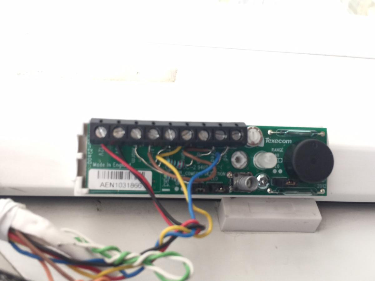
I am using the Texecom Premier Elite Compact PIR model ACD-0001
On the diagram supplied with the Pir it shows that one terminal is n/c and the other is 24 dc and together they are 50mA, am guessing the tamper and alarm wire should both be inserted in the 24dc terminal?
Will confirm on the resistance of the door contacts when i get another chance, it's closing time......
Are there any programming details I need to change?
-
On the panel it shows secure 2k2, when I open the door nothing changes.
on another note the Pir shows 4k8 when there is activity, I don't believe this is normal? There are six terminals in the PIR and I have used 1 for tamper, 1 for alarm -Aux and + aux for power and the jumpers for the resistor values, Should the wires go in any particular terminal for alarm and tamper ?
Multiple Reed Contacts Fsl
in !!..DIY Installers..!!
Posted
Would it matter if the contacts do not have a specific tamper terminal? I am using the CQR 1 Reed 5 Terminal Surface Contact Grade 1