_2d2230.png)
_5a42ce.png)

fiscoking
Newbie
-
Joined
-
Last visited
Everything posted by fiscoking
-
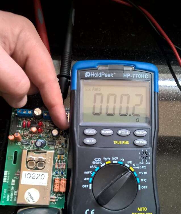
Update to the random tamper problem. Some of the PIR switches had a high ohm reading. I opened up each PIR in the circuit and put an ohm meter across each tamper switch, then closed the switch. Some of the switches read 100s Ohms even with the contacts closed. What I found odd was that repeated pressing of the tamper switch lowered the resistance. I could see it drop with each press. PCB inspection didn't reveal any dry solder joints (sometimes the joints crack) but re-flowed the solder on all switch legs and the contact block just in case while I had the PCB out. Each has a closed resistance of 0.1 Ohms now, so all good and no tamper alarms since. These PIRs were first sold in 85 and I think they had a 10 year run (Honeywell IQ220), so they're between 30 - 40 years old. I know switches need a 'wetting' current to break through the surface film resistance on a contact, so it might have been something to do with that given the time in service. I'll replace all the PIRs if they become a problem, but they're fine at present. Never seen that fault before. MrHappy>When an alarm is fitted by a proper alarm co. they do boring stuff called commissioning ...... Also measured the full circuit tamper resistance and left a note in the control panel for future fault finding. A good idea. Thanks for all the replies.
-
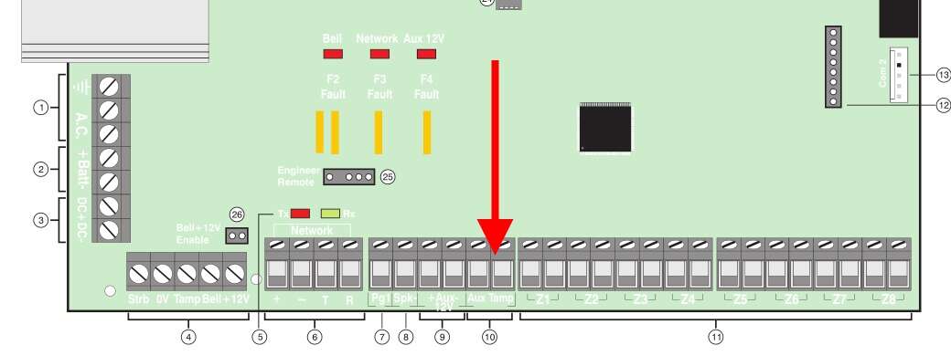
>>What's wired into the AUX Tamper? All of the internal PIR tampers are daisy chained (serially). So about 10 PIRs. But they only use micro switches for the tamper. Difficult to see how any of those could malfunction. Could also be a loose connection. I just wanted to know if the 'AUX Tamper' on the PCB was the same as 'AUX 0'. As James Wilson said above, I might have to open the case on a PIR to see if I get the same warning. After that, I'll jumper the tamper on the main PCB and see if I get the same problem. If I do then it's an issue with the main PCB and not any of the tamper switches or wiring.
-
Hello, Got a 'AUX 0 Tamper' out of the blue today on a remote LCD keypad. No changes to the alarm, which has been installed for about 17 years. Battery 12 months old. The premier installation manual has this on the event log description: AUX # Tamper An Auxiliary Tamper input from device # has been activated Which doesn't say a lot. Q> Does this mean the Aux Tamper circuit on the main PCB has gone open circuit? picture below. There's another tamper for the bell box, but that has its own event log message, as does the control panel lid. It's an intermittent fault, so hard to trace. Want to make sure I'm looking at the correct circuit. There were no self tests in the event log. System voltage is correct so the regulator hasn't gone either. Thanks.