_2d2230.png)
_5a42ce.png)

spammy
Newbie
-
Joined
-
Last visited
Everything posted by spammy
-
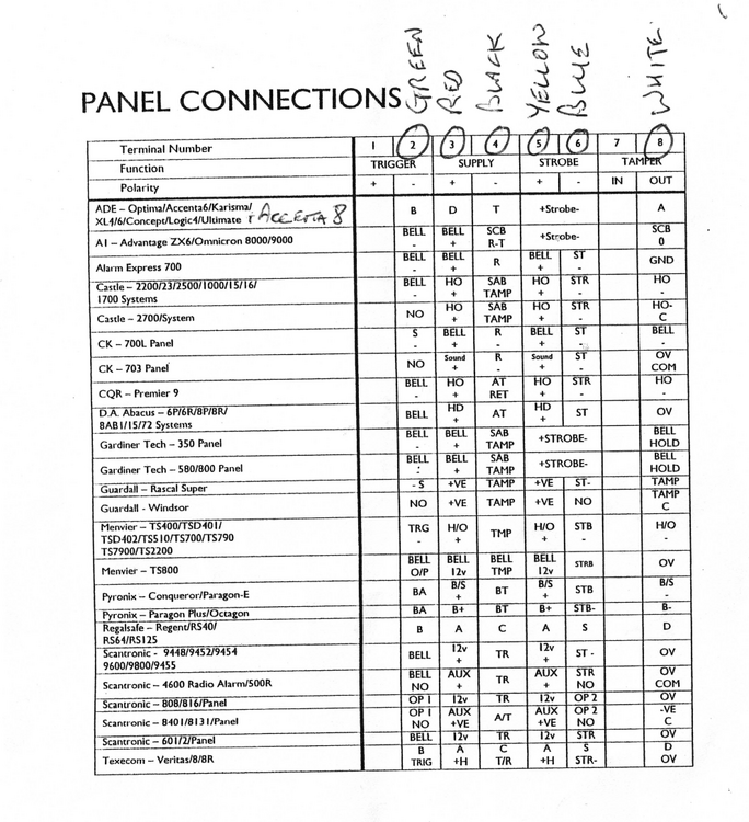
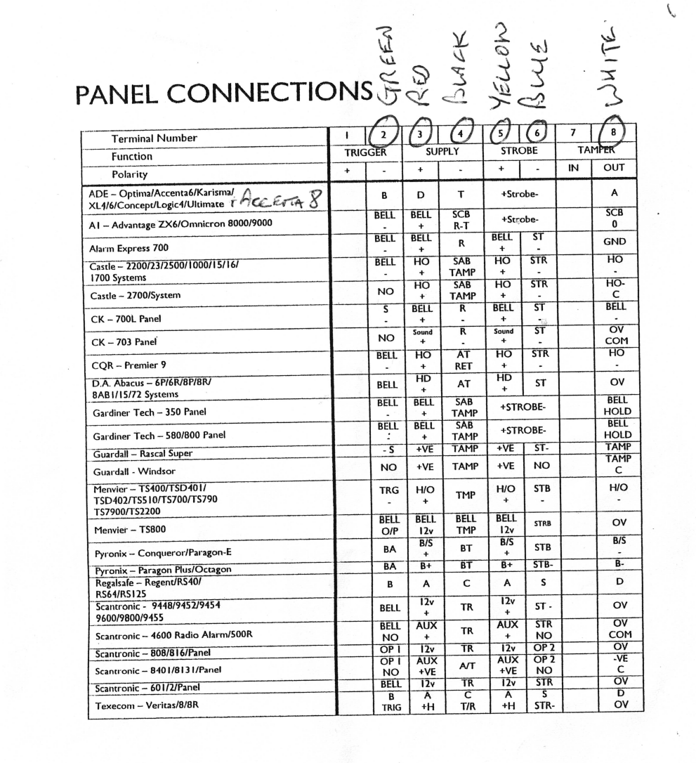
In the diagram and table in the first post, we are instructed to connect the bellbox tamper to the panel ground supply, and the bellbox ground supply to the panel tamper return. I am asking if this is deliberate, or a printing mistake.
-
Thanks for the confirm, that's what I concluded. The question is whether the installation instructions meant to swap the connections as labelled (perhaps there is a reason known to the industry for that) or if it is a mistake in the documentation.
-
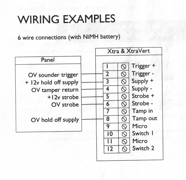
I wasn't clear. The instructions as written suggest to: 1) connect the bellbox "tamper out" to the panel's "Supply 0V" 2) connect the bellbox "supply 0V" to the panel's "Tamper return" By their names I would have expected them to be wired the other way around, however the second table seems to suggest this wiring for all panels listed. I understand that it's the same ground, but if this doesn't matter than why is there even a tamper return? I have since experimented with these terminals at the panel end and during day mode if I disconnect: 1) The Tamper Return, then the alarm fires with a tamper alert (internal siren, tamper warning and external strobe). 2) The 0V supply, then the alarm fires with a tamper alert (internal siren, tamper warning and external strobe). 3) Both Tamper Return and 0V supply, then the alarm fires with a tamper alert AND the external siren sounds. This all seems as expected (as #3 simulates a cut wire and the bell box battery kicks in). My theory is that the tamper return is ONLY signalled by the bellbox when it keeps the main supply but is opened, which at this point I don't think I can test without a ladder and hearing protection :). If so, then my suspicion is that the tables above are a misprint, but that it doesn't appear to matter which way around they are wired since the effect at the panel end is the same (as you say, a tamper alert in the case of a signal or cut wire).
-
Panel: Accenta8 Bellbox: Flashguard Xtra While reading the installation manual of the existing alarm above, I came across the following: The installer at the time kindly scribbled down his wiring notes and it is indeed wired as the above. I considered that this might be a printing error, except another table seems to corroborate it (this panel is at the top of the table and uses those TADB terminals): When searching for similar wiring diagrams, they seem to be wired in the expected way, ie tamper and 0V supply switched. My questions: Does this matter? Does the 0V Tamper return behave the same as the 0V supply voltage? Is the tamper return solely to let the panel know that the bellbox may have been opened (as opposed to cut)? If wired this way, is this behaviour lost? If I wanted to test the behaviour at the panel end, what's the best way to go about it? What should I expect from such a test?