

_2d2230.png)
_5a42ce.png)

Yassine
Member
-
Joined
-
Last visited
-
Thank you for advice you are alright I'm computer engineering and I'm missing basic of electronics Currently I need help to get just for this siren to work I want to know the wire from siren to control panel that I showed how they look like
-
Thank you for your help ?
-
I Put jack in off for LC stay the same
-
Turned on but still the same When I wire the siren with 12v and 0V from control panel or from Power Supply 12V DC it make sound and the green light flashing and than stop wait for trigger from control panel I tested with mini siren that is work with audio jack (Siren+ , Siren -) it is working normally when there is trigger something in the linking I have did from control panel to siren is wrong
-
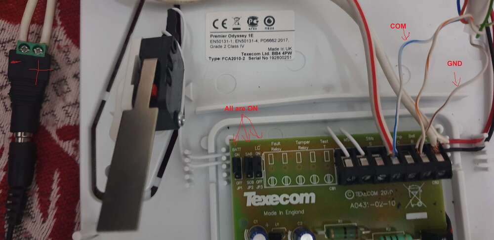
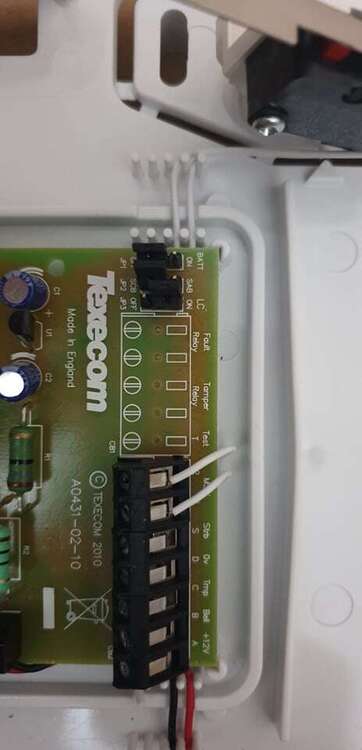
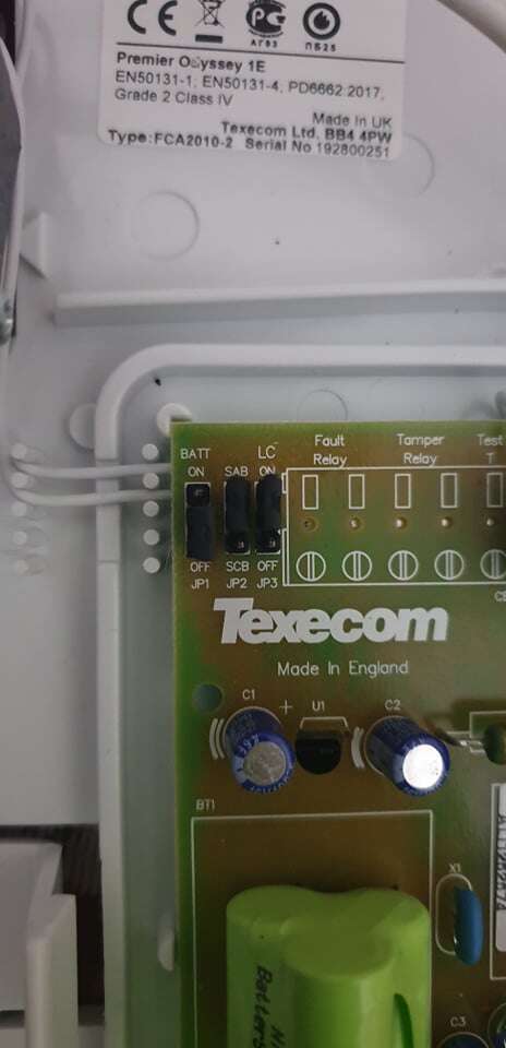
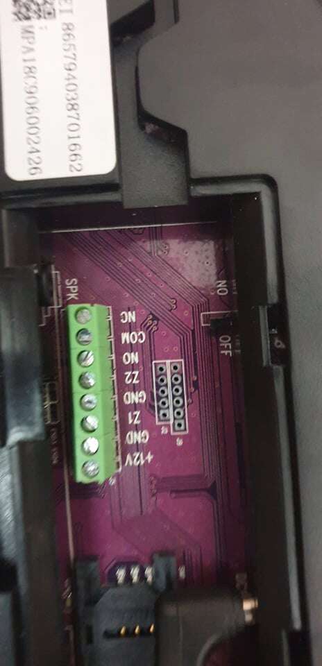
I'm trying now with Power Supply 12V DC 12v ----------------------------> 12V+ 0V ------------------------------> - and from control panel I wired Siren Control panel Bell ----------------------------> GND STRB ------------------------> GND nothing happened when I trigger the siren from control panel or PIR triggerNothing happened when I triger the siren from control panel or when PIR triger I think I have to use the Siren+ and siren- I tried Siren Control panel 12v ----------------------------> 12V 0V ------------------------------> GND AND COM Bell ----------------------------> NO STRB ------------------------> NO ANd Siren Control panel 12v ----------------------------> 12V 0V ------------------------------> GND AND COM Bell ----------------------------> COM STRB ------------------------> COMI don't need TMP for now I linked Siren Control panel 12v ----------------------------> 12V 0V ------------------------------> GND AND COM Bell ----------------------------> NO STRB ------------------------> NO Nothing happened am I wrong in the linking ?I'm lost in the linking The control panel wired ports: *) NO - Relay port (normal open). It will be triggered when the system is alarming. *) COM - GND port of relay *) NC - Relay port (normal close). It will be triggered when the system is alarming. *) 12V - Positive end of 12V output *) Zone2 - Wired sensor 2: support both NO and NC *) GND - GND *) Zone 1 - Wired sensor 1: support both NO and NC *) GND - GND *) There is audio jack for siren S+ S- Siren Control panel 12v ----------------------------> 12V 0V ------------------------------> GND Bell ----------------------------> ? STRB ------------------------> ? what I have to link for bell and STRB ?Do you mean 12v from control panel is insufficient ? because Last year I linked with wired siren from different brand with 12 v from control panel of this gsm alarm and it is working great but with Odyssey 1E I don't know how or where I am wrongThe Manual of Odyssey 1E http://www.moretonalarms.com/pdf_engineer_manuals/Odyssey.pdf The Manual of Wolfguard GSM Alarm (this is different model but almost the wired zone are the same) http://www.wolf-guard.com/app/file/8 I tried but nothing happened except the light of the siren is greenHi All, I did read many post on the forum before starting this one so please excuse me im repeating someone else question. Im linking Siren Texecom Odyssey E1 With Wolfguard GSM Alarm I don't know if they work properly Could someone tell me if it's possible to pair this siren with this control panel and what links I have to follow Any help would be appreciated.


Important Information
By using this site, you agree to our Terms of Use.