

Steve23
-
Posts
20 -
Joined
-
Last visited
Content Type
Profiles
Forums
Events
Downloads
Gallery
Blogs
Posts posted by Steve23
-
-
Hi guys.
I'm installing my new Reson8 bell box and I have wired the wiring into the control panel (Honeywell flex) as per the instructions but there was no +12v in the terminal block for the bell in the panel so I put that wire into the intellibus +12v terminal just above it.
The bell box has been installed on the wall with the cable fed through but it's not been wired up yet as the weather changed.
But I did test the tamper wires and that worked and thought I would read +12v from that one.
I thought the bell monitored for power loss so presumed the 12v would be permanent am I right or wrong.
Thanks.
-
On 17/04/2020 at 12:06, GalaxyGuy said:
I'm currently working on a virtual RIO module as part of something that I want for my own home automation. I'll sell this for the bigger panels like the FX100+ and GD96 upwards, as they have lots of links available. The virtual RIO sits on the RS485 bus and will consume 4 addresses, giving 16 outputs and 32 inputs in virtualised form. On my own system, I currently have lots of outputs programmed to switch lights, heating and garage door Etc, but I either control them from the app, or guard codes. I've been looking at OpenHab, so would like a way for linked zones with virtualised outputs to provide the OpenHab 'things' with status update calls over IP. There shouldn't be any reason that the virtualised RIO cannot send the calls to any other controller, it's just a matter of the appropriate protocol.
This is basically what some of these other hardware vendors do for Vista, but instead of the compatible device, they physically hook into the existing zones and outputs wiring. This would cause an issue for the Galaxy, as it uses balanced circuits, so any external influence on the circuits would cause problems. The virtual RIO will only need connected to the bus and an Ethernet connection, so a simple addition. Since the inputs and outputs are programmable, it's entirely up to the person who configures the system as to the level of control allowed. An input call to the virtual RIO could set a zone as active and in turn fire another physical panel output, or set the system. Basically anything that the panel is capable of. For me, I think the timers and sequence based logic is limited on the Galaxy, and that's where the home automation excels.
I like the sound of that

I was hoping for some way besides Konnected to link my Flex into my SmartThings.
I was hoping I could do it a similar way to a standard 12v doorbell I have.
So I have a Xiaomi ZigBee push button thats on my SmartThings setup and it has contacts on that replicates the button been pressed, so I connect them to the led on the bell receiver so when the bell goes of it activates the button and then I can do what I want with that within SmartThings.
I wouldn't know where to start with the flex I just followed a guide to do the bell.
-
1 hour ago, al-yeti said:
Does flex have anything in menu to say banner? That's what was on older versions
Set display , probably not unless switching off the en thing and it allows it , I am guessing
Is keypad visible from outside to know it's set or not? As that would be disadvantage if you get me
Ah yeah you've got a point there about the keypad being visible didn't think about that.
I'll have another look in the display settings see if I've missed it.
Thanks
-
Hi.
I've been testing my Galaxy flex 20 still and everything seem to be working fine now and arms/disarms fine etc.
Can I edit what is displayed on the keypad banner at the moment it's just showing the model name and number.
And also when the alarm is armed is there a way of having it display on the keypad that it's armed ?
I've looked through the manual but can't see any mention.
Cheers
-
15 hours ago, tinnitus said:
So we had to use areas because the client had an office space split over 2 floors and wanted more flexibility.
I can’t see a good reason to use it at home unless you had a completely separate area. I’d say part set and full set are all you need.
what did you need to do?Thanks,
No there's no specific area I need separate.
I'll leave that alone then

-
2 hours ago, james.wilson said:
I'd start a new topic based on your requirements
I didn't want to spam the forum with new posts.
I don't really have any requirements just saw him talking about it so thought I'd ask.
-
Hi @tinnitus
I was thinking of setting groups up on mine but couldn't see what benefit I would get.
It's it only really helpful if you have a keypad upstairs,
I'm only having them downstairs at each door.
-
14 minutes ago, datadiffusion said:
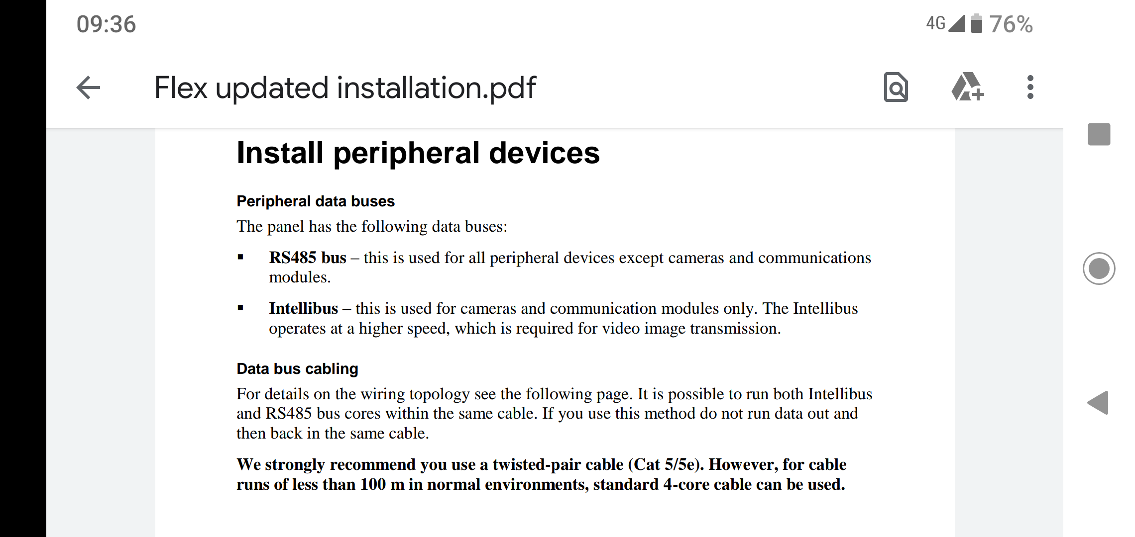
Ah that's a new one, I'm not big on Galaxy/Honeywell, but IIRC they used to recommend screened Belden cable, again only for long-run peripherals.
In fact, using any solid core wiring is a really bad idea IMHO, from an installer 'boots on the ground' PoV.
I've just looked at the old installation manual for the version 1 firmware and it does recommend to use Belden on that one.
So they've changed it for some reason.
On the updated manual it says use Belden if over 100m

-
1 hour ago, datadiffusion said:
Are you sure? I'd be amazed.
It may mention screened cable for keypads and nodes, but this is still flexible type.
Ah yeah I think I read it wrong its in the Peripheral devices section.
-
1 hour ago, SecureAlarms said:
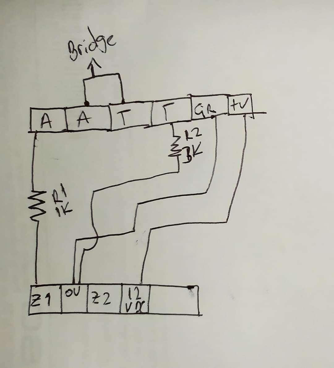
1k across the A + A. 1K across A + T. 1 Core in 1st A. Second Core in Unused T.
Thanks I'm starting the understand things now.
I like your explanation it's so simple even I understand it.
Yeah that diagram was what I got sent by someone which confused me as it contradicted everything I'd been reading.
-
28 minutes ago, MrHappy said:
No, I'm in the English, we don't do that sort of thing...
In his part of the world they probably, have dead dogs in the street, open sewers & wire alarm funny....
Was it Prestatyn ?
That town has changed from the email notification I got
I do have a dog who likes to sleep and not notice anything or anyone lol
By the way are these Pet immune sensors a gimmick or do they actually work for dogs.
-
Thanks for the info guys.
Yeah i realise there's more to it then I thought
.
I naively thought the connections would be similar to what the kepad was
A to A,
B to B etc
Can I double check with you guys, I asked the question at the same time on a Facebook group and someone suggested putting the resistors inline and not into the connections on the sensor is that how you would do it ?
I'm talking to him through Google translate so thought it would be a bit tricky to ask him.
He sent me this picture.
-
15 minutes ago, al-yeti said:
Panel just wire the two cores to a zone and that's it , the panel uses two cores for the zone for tamper and alarm , which is why eol is done at the sensor
Thanks.
I'm not great with this can I just check,
You are basically saying I can use either of the zone connections as long as the resistors are right in the sensor ?
Can I also ask you about the diagram above, it shows the -V joining one of the alarm wires on the sensor side and then onto the 0V on the panel..
Is that the normal way of doing it then
-
7 minutes ago, Logan said:
I reccomend you you 8 core alarm cable. Using phone or cat 5 Ethernet network can cause problems
Thanks I have bought alarm cable just waiting for it being delivered.
Although the manual does recommend Cat5 cable.
Although I've only ordered 4 core as I thought that's all I need.
-
19 minutes ago, james.wilson said:
Fault is optional for higher grade detectors just wire it as you have for alarm and tamper
Thanks for the reply.
So how do I tell which is the tamper connection and which is the alarm connection on each zone on the panel ? As it doesn't label them like on the sensors.
-
Hi all.
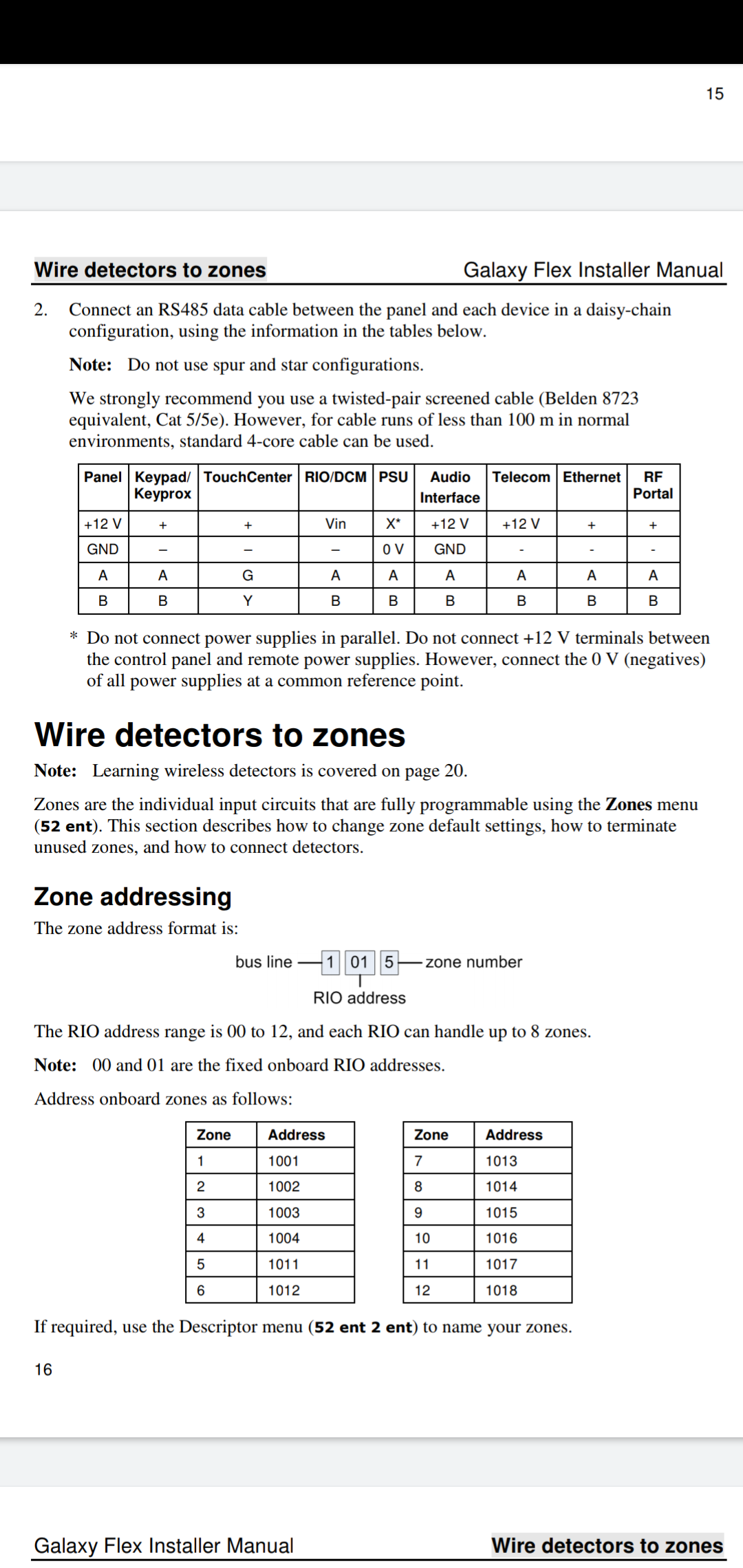
I best start of saying I'm a complete beginner when it comes to alarm systems as you'll probably guess. I have a Honeywell Flex 20 and a keypad and a couple of budget PIR motion sensors to test out wiring EOL before I buy more (better quality) and install.
On the manual its shows 8 connections on the sensor.
2x Faults,
2xTamper,
2x Alarm
2 Power.
But on most of the motion sensors I've seen they only have 6 connections.
2xTamper
2x Alarm
2x Power
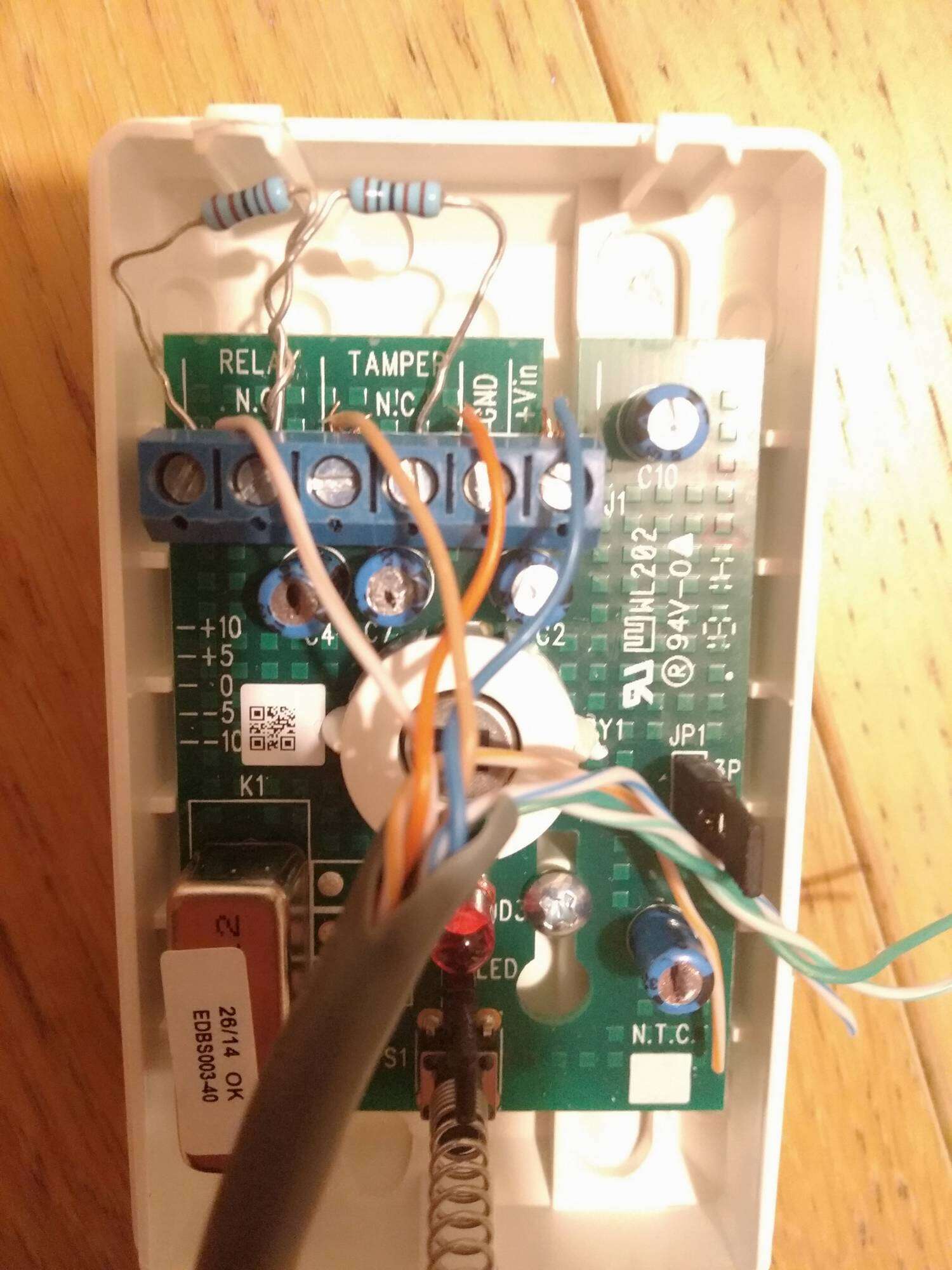
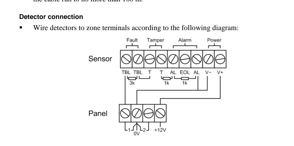
The manuals showing me where to wire the resistors including into the 2 fault connections but how do i wire the resistors if I only have the 6 connections?
I watched a couple of YouTube videos and I'm thinking I may have it right but now I'm not sure how that wires to the board as again the manual shows the fault connections being wired to the board.
I've attached a couple of pictures from the manual and one from the sensor I think it's wired right, you'll have to ignore the wire colours as I'm using old cat5 cable for testing.
Also another part what should be easy is if I'm not using a zone on the alarm I'm not actually sure where to wire them.
Sorry for the fact questions and thanks for any help.
-
4 minutes ago, james.wilson said:
Do you have the software?
Not the Honeywell.
Just trying to make basic coms see what that gives me.
-
15 minutes ago, james.wilson said:
What are you looking to do with it?
Just to have a mess around in the settings until my Keypads arrive.
I've just got the control panel and 2 sensors at the moment so testing things on the table.
-
Hi guys.
I'm wondering if any of you know where I can get the USB drivers for Windows 7 so I can connect to my Honeywell galaxy Fx20.
I've plugged it in and it shows searching for "FX panel" drivers then comes back none found and googling keeps showing Samsung galaxy phones
Thanks for any help.
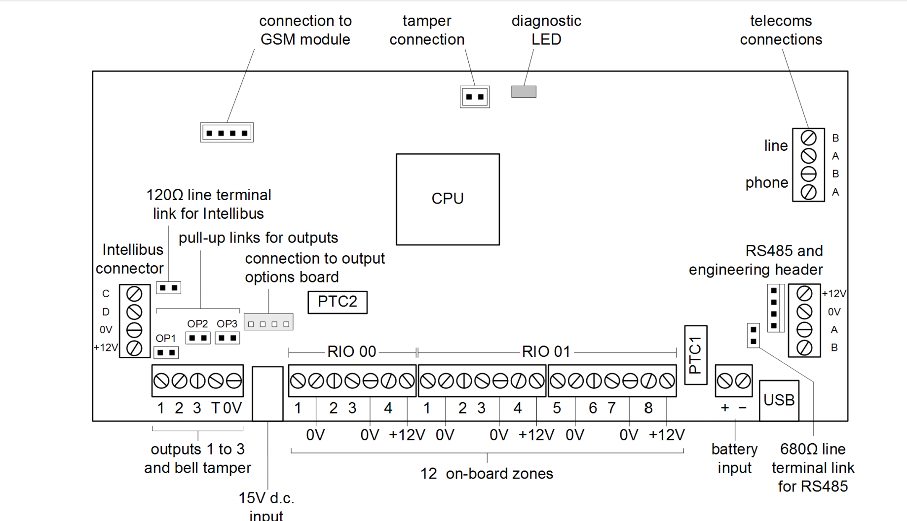
Does the Reson8 bell require permanent 12v live ?
in Control Panels (Public)
Posted
Thanks
I'll check my wiring