_2d2230.png)
_5a42ce.png)

Alan_in_Wilts
Member
-
Joined
-
Last visited
-
-
Thanks. An ebay search for that tends to bring up the simple screw choc blocks but paging down also showed 4/8/12 Position Barrier Block Terminal Strip Connector with 1 UK seller on ebay but plenty sellers in Hong Kong & China. Not quite the same as the PCB versions but similar and without the pins. This ebay item 312723313871 even comes with a strip of linked spade terminals to convert the barrier connector into a bus. I now recall using one of these barrier connectors some years back to update the antiquated wiring on an old Connoisseur BD2 turntable which I then fed via a pre-amp to a new digital hi-fi - old technology married to new!
-
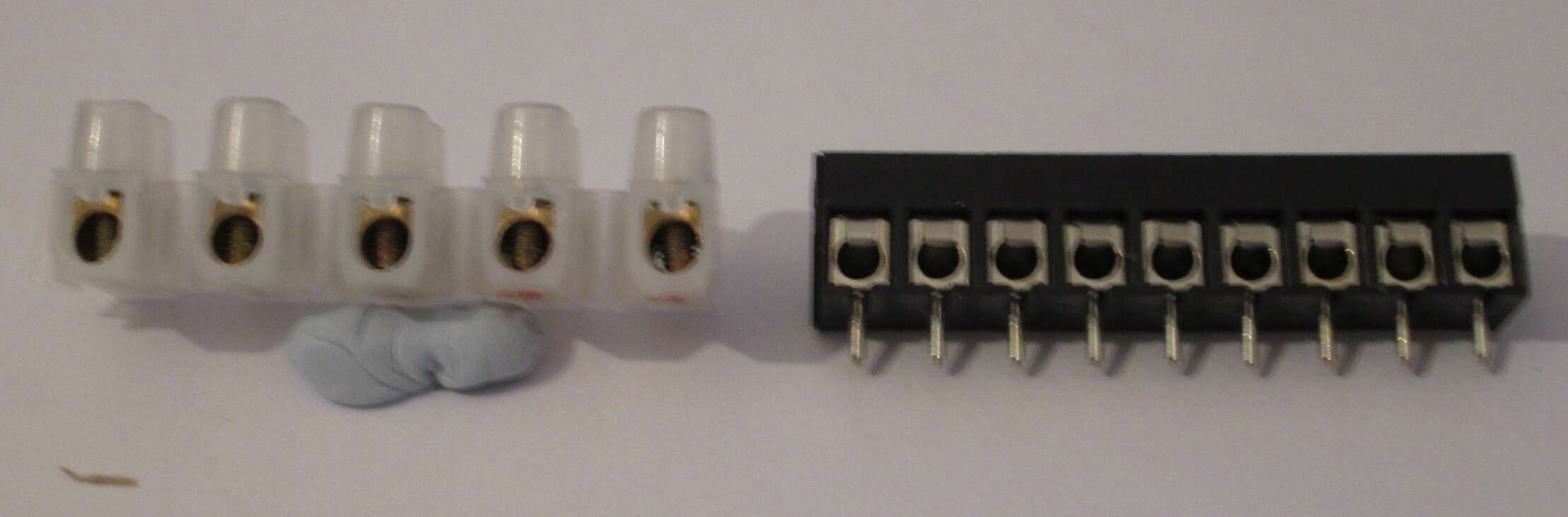
I own up!! I ran out of alarm cable and used some Cat cable I had. I don't recommend this as the individual wires are too thin (24ag) to grip in the contacts when there is, say, a resistor wire also in the contacts. Theoretically I should be able to pull through another alarm cable but it's now stuck, so it will have to do. It's only about 3m long. One thing I forgot to mention is I found the +/- contacts on the Panel rather full with all the cables (a downside of wiring each sensor on it's own zone). So I made a bus using a two connector strips fixed to a piece of veroboard which was then hot glued onto a piece of self adhesive conduit channel. Only took a few minutes. I think TexeCom should provide this. BTW, what are these contact strips called with the little plate to grip the wires (as opposed to choc-blocks with just a screw to grip the wires)? I had quite a problem finding them on the internet not knowing what they are called. The ones I bought had veroboard pins (which I needed) but I could do with some without pins simply to join cables. The ones with just screws don't work easily with thin wires. Yes, one can snip the pins off but it leaves a sharp residual.


-
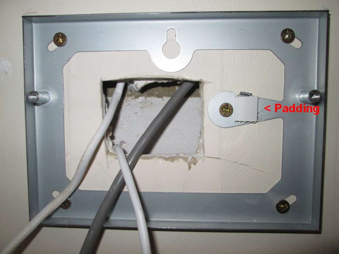
The RKP is on a flat plasterboard wall. I considered bending the tamper leaf but considered that too risky given the cost of the RKP. I don't think a washer would fix it, as the problem was not the backplate protrusion being too far back but too high. Photos: I had to add more padding until it was level with the top of the protrusion:


-
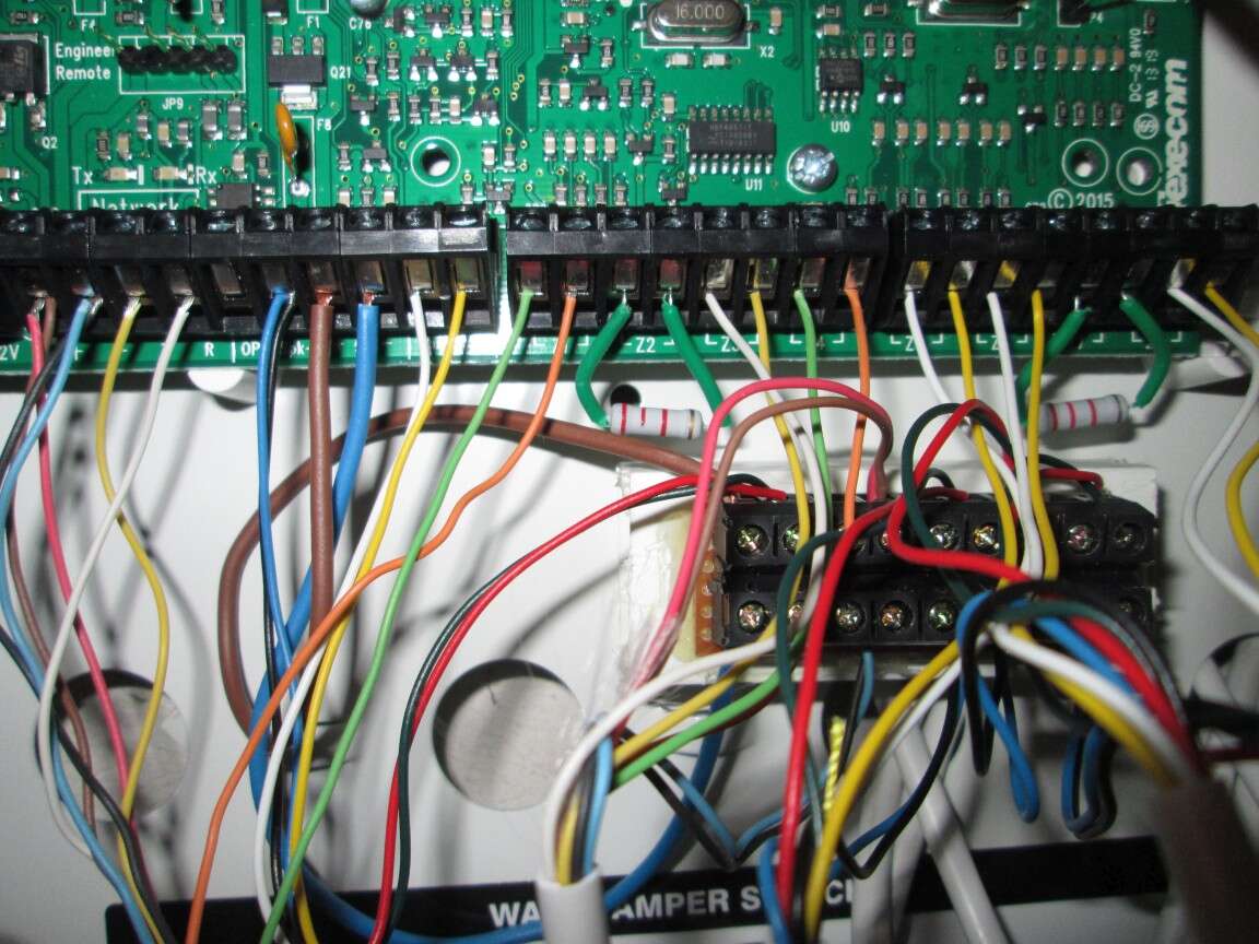
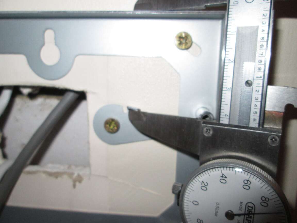
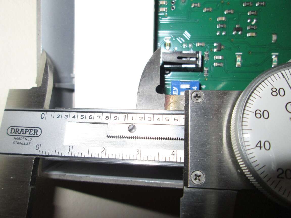
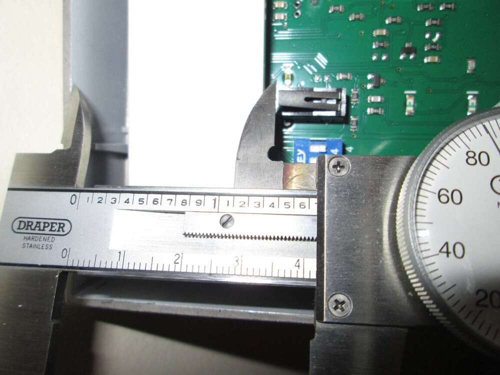
The 2k2 resistors duly arrived along with an endoscope. I changed the 4k7 to a 2k2 and change the configuration to Double EOL. I also changed the RKP Z1 & Z2 to map to Z23 & Z24 on the panel, freeing up 2 panel zones for future use. I also replaced the 4 core cable to an 8 core and therefore put the shock on a separate zone. It was a pain threading the cable. I was half expecting vertical stud work but there was none, instead dolups of plaster sticking the plasterboard to the metal lintel. While the domestic authorities were out I drilled 3 x 16mm access holes but failed to complete the job and fill the holes before said authorities returned!! On firing up the system I still had one error: tamper on the RKP. Removing it and pressing the tamper switch cleared the fault so using calipers I measured the distance from the edge of the RKP to the end of the tamper switch and the corresponding distance from the edge of the backplate to *past* the raised protrusion. Both were 41.9mm - i.e. the tamper switch was just missing the protrusion. So I added some packing to the back plate until the fault cleared on reassembly. I've sent photos to TexeCom. Now it all finished bar making good the holes. Next step is to get the Android App working and linking to my Raspberry Pi. Many thanks to all who have helped, especially sixwheeledbeast and MrHappy
-
I thought of that but not possible as I can see that the cable has been fixed with cable clips. Presumably in a new house all the cabling is put in place after the stud work is done but before the plasterboard is fixed. I might buy a cheap endoscope to explore behind the plasterboard, otherwise I will skip the shock. Whilst Texecom make the door switch with shock their WinTex software doesn't seem to have a Type setting for it and the leaflet with the door switch has no wiring or configuration examples. A plain door switch is Type Entry/Exit and a plain shock would I presume be Guard but what is a combined door switch & shock? By putting the shock on a separate circuit (and zone) it can be Type Guard leaving the door switch and tamper as Entry/Exit. Do say if my thinking is screwed! Thanks for your support.
-
Penny has dropped. Thank you! That did cross my mind but then I noticed that on open circuit the RKP Zone Status said >65K so I thought the threshold was >65k. Also crossed my mind that the panel might see shock as door open. I only bought the door with shock sensor as it just a few pounds more than the basic door sensor but that was before I realised the existing cable was just 4 core. I've been tapping away on the plaster board trying to determine if I could route a 2 core cable so the shock can be on a separate zone. Good idea. Thank you. I've only 1 zone spare at the moment though no plans currently for more detectors but your suggestion would give 3 spare zones. I'll look at github once I've got the alarm system up and running. Thanks again for your helpful suggestions.
-
Ah! I knew I was at risk of someone mentioning wi-fi I've an aversion to it generally and read that burglars now having jamming devices. Plus problems with range and walls. Similarly not happy with keyless cars. Hired a car the other day and had problems. I do have wi-fi but it's normally off and comes on if I use the tablet (rarely) or guests stay but most people (including myself) now use mobile data as the packages have generous data allowance. Back on topic, the Ricochets use quite expensive batteries which need to be properly recycled at end of life. But I admit, not running cables is a big advantage in time and upheaval and I can see why professional installers use this option. PS Saw this youtube video recently of a Scottish chap installing a network in his new flat - ended up like Swiss cheese with all the holes he drilled! I think he might admit to being a bit of a lunatic! but he went for wi-fi when installing a Texecom Premier Elite 64-W (another video)
-
As I said, a puzzle for a wet weekend - i.e. a non serious posting. I shall just ignore the cable for now. I've already discretely run 3 more alarm cables without upsetting the domestic authorities! (on top of another 5 Ethernet cables I put in at the same time - total 28 Ethernet ports and counting! ).
-
-
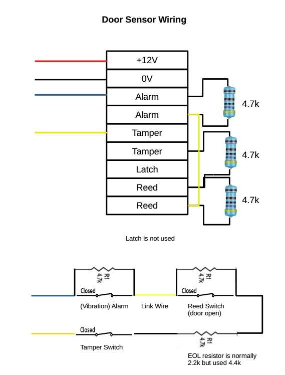
They are in series so isn't it 4k7+4k7 = 9k4 which conforms to the Zone 1 Status of 4k710 when the door is closed (EOL resistor only) and 09k390 when the door is open (EOL+Alarm). As I said, it is configured with option 7 on page 60: 4k7 alarm resistor and 4k7 EOL resistor and as per the circuit diagram on page 32 EOL which shows them in series. Anyway, I shall await the delivery of 2k2 resistors and that will eliminate this potential issue! Ref: Resistors in Series
-
Puzzle for a wet weekend House was built in 1997 and was pre-wired for alarm system but the 1st owner did not install. When we bought the house in 2001 I hid the ugly cables in electrical surface back boxes. At the time I presumed the 4 cables terminating in the garage were: 1. door switch - cable above front door 2. keypad - cable to side of front door 3. lounge - cable for lounge PIR 4. dinning - cable for dinning PIR I wondered about the cable for the external alarm but never saw any cable in the loft - much of the loft was boarded over. Fast forward to fitting my Elite 24 and I find: 1. door switch - cable above front door is only 4 core and leads to keypad outlet 2. keypad - 8 core cable to side of front door and links to garage cable 3. lounge - 8 core cable as a loop (no end) for lounge PIR and links to garage cable 4. dinning - same 8 core cable as the lounge So that accounts for 2 of the cables terminating in the garage (keypad and lounge+dinning). The 3rd no doubt does go to the loft for the bell. Any ideas what the 4th cable could be? Note: we've now decorated the whole house and no cable has come to light or any indication of a hidden cable. There is no reason while the first owners should bury one cable when they were quite content to have the other cables hanging out of the wall. Alan
-
Thanks guys for a very fast response. According to the manual (page 60) the Elite's can be configure using other values. Anyway 2k2s should arrive on Tues. There were no resistors with the panel. Page 60 of the manual, option 7: Yes. As I said in my post "RKP Zone 1 is mapped to Zone 1 on the Panel and RKP Zone 2 is mapped to Zone 2 on the Panel . " Zone 1 was then defined as 4k7/4k7 Some of my other sensors do give a nice click with the tamper button That was my plan. Connect RPi to Panel output connections and then send email to SMS service. Would be nice if the Elite could be programmed to send MQTT to the RPi via the SmartCom and the LAN rather than build a hardware interface. That's news to me I thought one needed to buy the GSM board to send SMS direct from the Elite. I need to hunt for more manuals on the Texecom website. I have signed up as an installer. Thanks again.
-
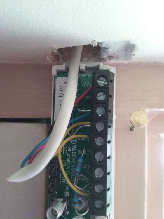
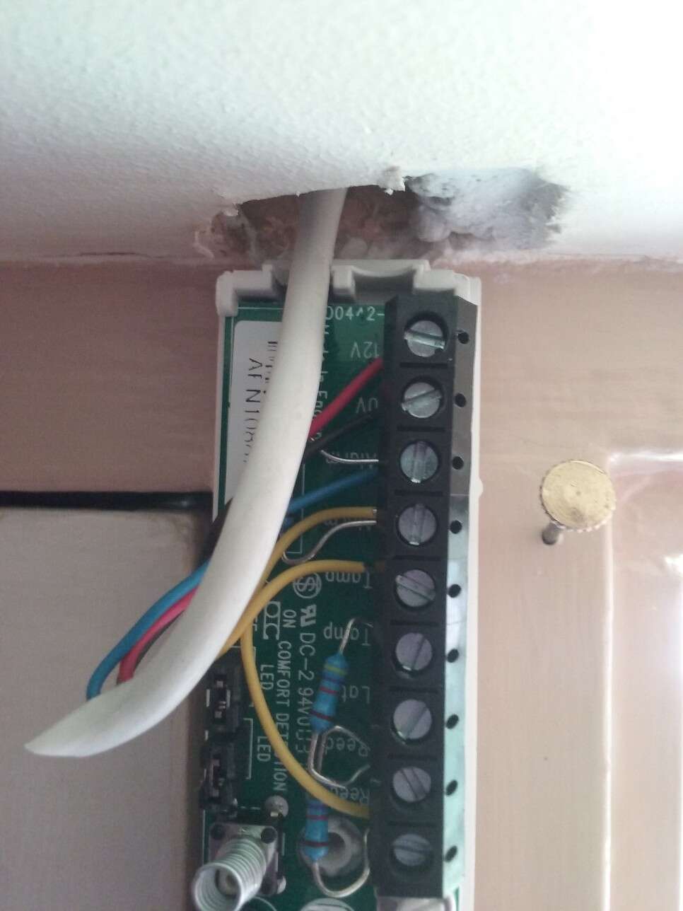
Hi, first post so please be gentle In process of installing Elite 24 with Telecom DBD-0171 RKP, Telecom AMQD PIRs, Texecom Impaq Plus Door Contact AED-0001, Texecom AGB-0002 Smoke Detector RR/4W, Elmdene, ELM-PA-G3-W Panic Button, Elmdene 16 Ohm Extension Speaker EXTSP-16T-W and a Telecom CEL-0001 Connect SmartCom with WinTex. The door contact switch is fitted to Zone 1 of the RKP and the Panic Button to Zone 2 of the RKP. Whilst the house was pre-wired I've discovered that the mean builders only installed a 4 core cable from the door to the RKP location so I had to put both the alarm and reed in series, each bridged with 4k7 resistors, and then as I didn't have any 2k2 resistors to hand I used 4k4 for the EOL and configured the door contact a Type 4k7/4k7 in WinTex. RKP Zone 1 is mapped to Zone 1 on the Panel and RKP Zone 2 is mapped to Zone 2 on the Panel . (pictures and diagrams attached). I have 1 fault: RKP 1,1 tamper - that's the door switch. In the RKP under Zone Status I get Zone 001 N1,R1,1 Secure 04k710 If I open the door I get Active 09k390 If I bang on the door I get Active 09k390 If I open the door and bang on the frame I get Active 13k920 If I remove the switch cover I get Tamper >65k (open circuit) This all seems fine to me but if I go to RKP Status I get N1,R1 Z1=T Z2=H Tamp=A Output=* i.e. Z1 has Tamper Activated. So why do I get a Tamper error if the Zone Status for that device seems OK? PS1 I do have some 2k2 resistors on order and will config as Double Pole/EOL but I don't think it will make any difference. PS2 not happy with the door switch build. The tamper switch does not have a positive click when being pressed or released. PS3 my background is 50+ years in IT from programming to programme management. In retirement I'm dabbling with home automation using RasPi, CAD, 3D printing etc. I have an LAN with over 30 devices on it. I'm more a mouse man than a soldering iron man! I'm looking link the Telecom system to my RasPi to switch on cameras when armed and send SMS when an alert. Thanks for reading Alan