_2d2230.png)
_5a42ce.png)

CR Alarms
Member
-
Joined
-
Last visited
-
Thanks that sounds reasonable, incidentally i had a look at the reverse of the pcb and the solder tracks to the bell circuit and aux output are huge at least 5mm thick, so i imagine they could quite easily sink 500ma. Thanks again, i believe my question has been answered. Mods feel free to remove my upload files or leave them on here its up to you.
-
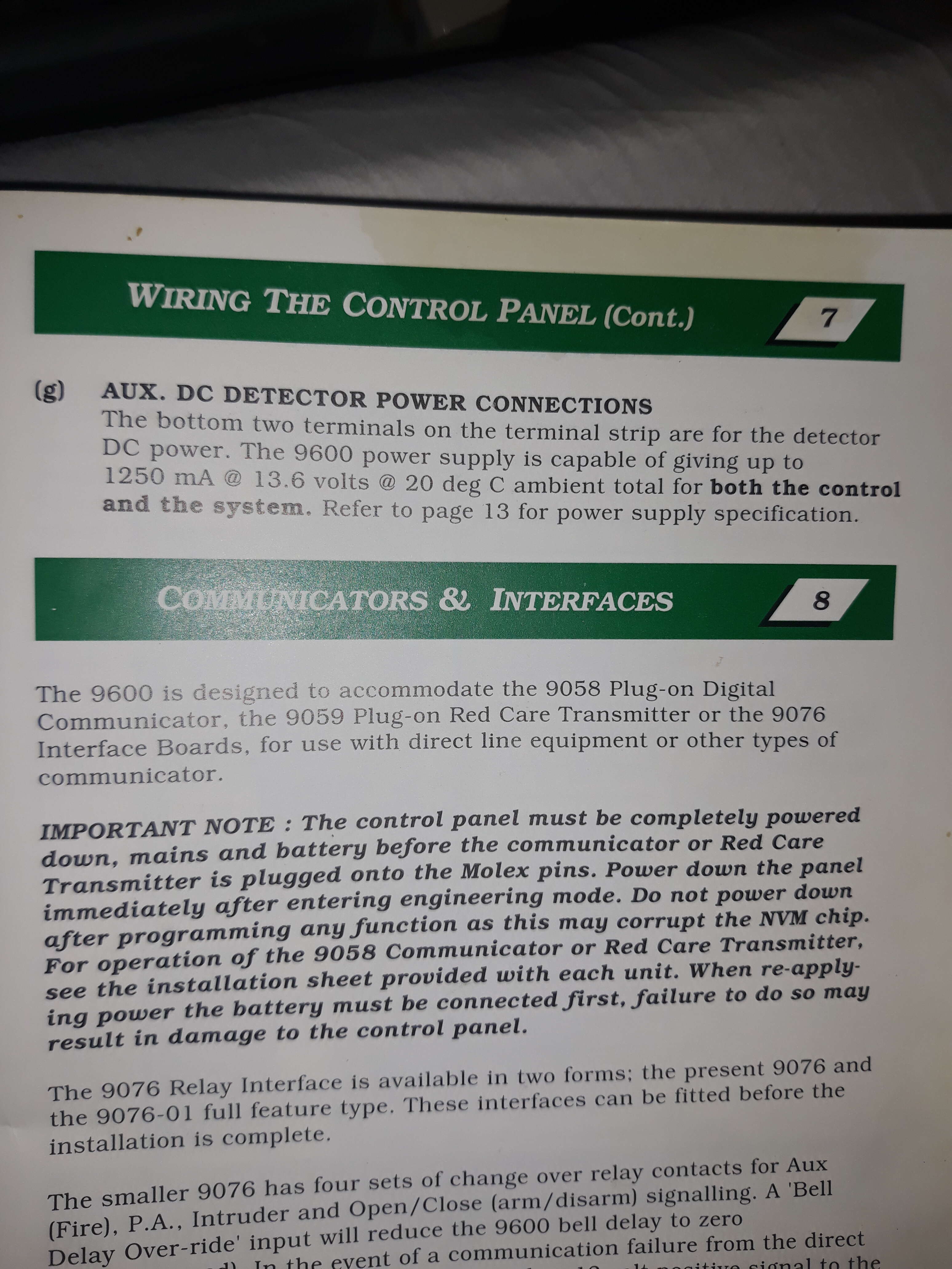
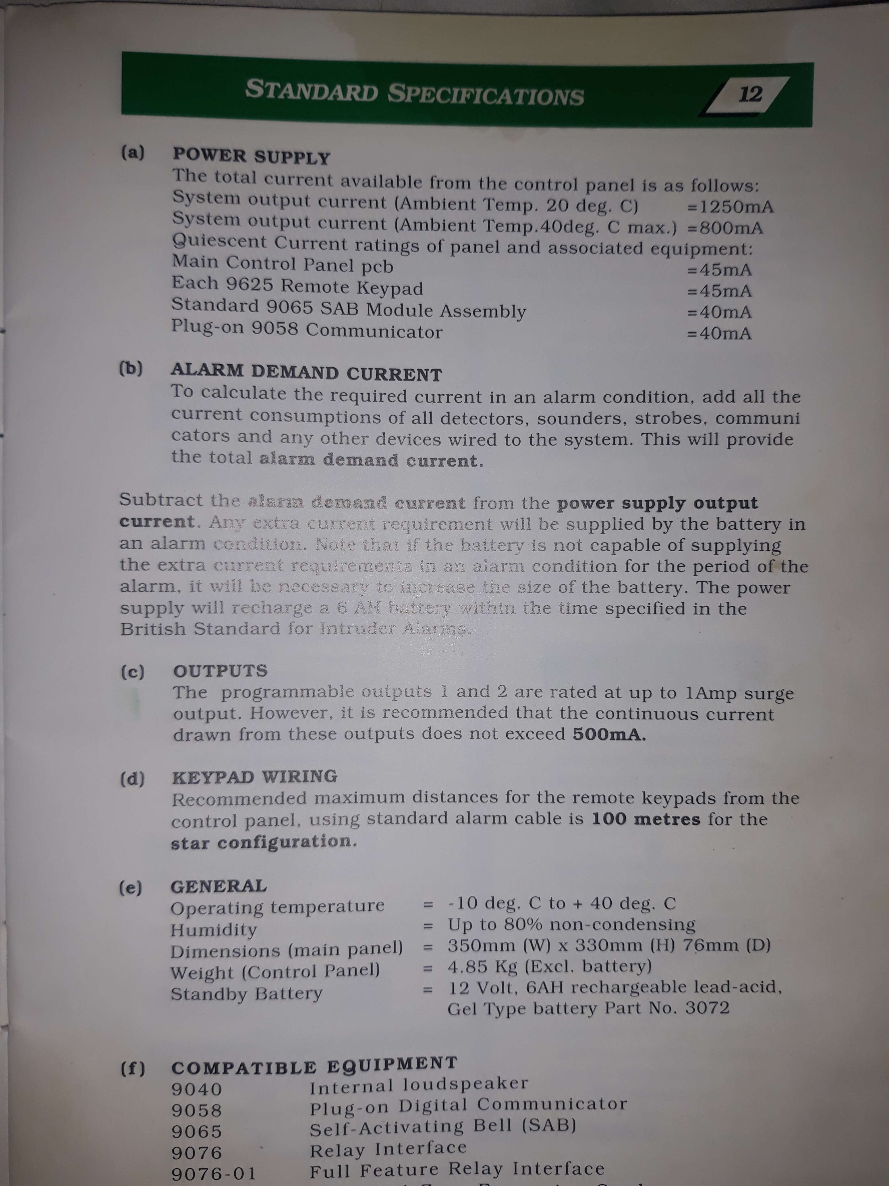
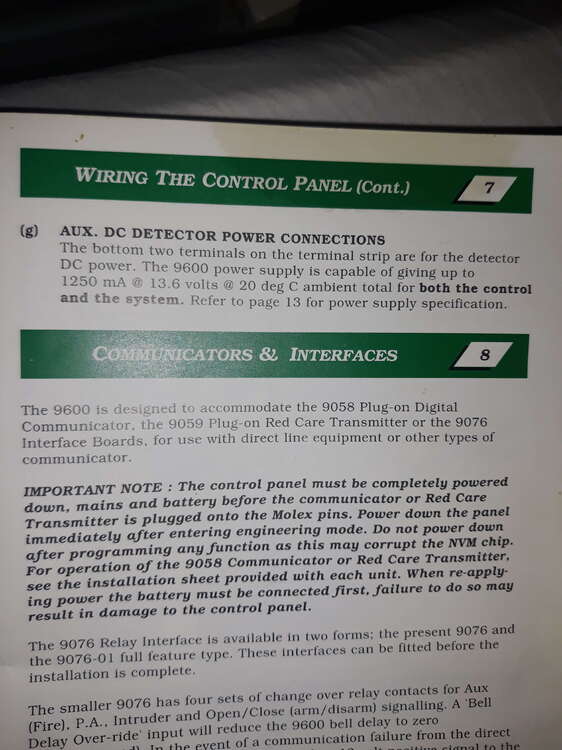
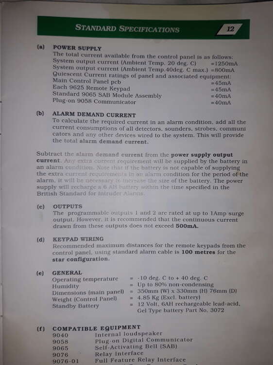
As we seem to have a full house, can anyone confirm if the 9600 12v outputs are individually protected by a polyfuse, or if its all commoned together and governed by 1250ma? So in other words the bell hold off circuit is not going to trip if i load 500ma on it? It should all be fine providing i stay under 1250ma, i will playing it safe by staying under 1amp, the total current will be 920ma worst case, if elm300 is taking full charging current(80ma). If anyone can confirm this, i will be out your hair and leave you all in peace. Here is another part of the manual to make this all clearer Thanks
-
You do have a point tbh, i rarely see anyone take any notice of a bell box sounding, the internal sounder i have at the moment is the elmdene speaker which is Loud but not quite loud enough to drive you out house hence why i bought the elm300 give the sound a boost indoors. Just one more thing regarding the panel power supply, does each 12v output such as the bell circuit have its own individual polyswitch?, if so what are they rated at? Or are all the 12v outputs commoned together and protected by one big polyfuse rated at 1250ma at 20 degrees and at worst case 800ma at 40 degrees? Cheers
-
Thanks, worst case i will scb both external sounders, do you think it would work in reality? The elm300 i intend add will draw 80ma max but i imagine once its onboard batteries are fully charged it will be even less than that. Did you ever use these panels? If so can you remember what the hold off circuit is rated at? Cheers
-
What do you mean exactly? The battery is the correct size for the panel (7ah), my system is not that loaded its 240ma in standby and 840ma in alarm. Cheers
-
Hi all, sorry to pester you once again, i managed to get hold of an elmdene elm300 it's an scb Internal sounder which will draw at the most 80ma charging current from the panel, can i safely add this to the system? I know from the scantronic 9600 manual it can supply 1250ma at 20 degrees, my total current in alarm is 840ma, so it will be 920ma worst case if the elm300 sounder it taking full charging current. One thing that has always baffled me is the 9600 manual does not say what the bell hold off terminals (0v and 12) are capable of supplying? Am i correct in thinking that the total load is 1250ma but you have to factor everything else on the system to determine how much you can draw from it? The load from both external Sounders take 420-430ma from the hold off circuit. Given i want to keep the total load under 1amp, am i correct in thinking the max that can be drawn from the bell hold off circuit will be around 580ma? How i worked this out was calculating the keypads panel, detectors and speaker, the total draw from these (speaker sounding obviously) is 421ma, taking this away from the power supply output i could potentially draw 830ma from the bell hold off circuit, obviously i want to stay under an 1amp so i will knock off 250ma, so in which case the max remaining current i can draw from the bell circuit is 580ma. Is this how the loading works for this panel? Or does the bell have its own polyfuse? If so surely the manual would mention this but it does not, so i can only think the 12v on this system ( aux ,bell hold off, ect) is all commoned together and the limit is 1250ma and you build the system ensuring you stay under this figure, for the being sensible i will be staying below 1 amp. Does this sound correct? Thanks Hope this makes sense, Here is the relevant info from the manual
-
Perfect, i just switch them round. Cheers
-
Hi again, i was just wondering out of curiosity if it is acceptable to switch the modes on my sounders the other way round, so the front unit is now scb and the back is now on sab, as i sure you know burglars will want to break into a house where they are less likely to be seen, in my case this would almost certainly be the back of the property, so with that being said is it better in my case to have an ear piercing loud sounder at the back (sab) and have the front sounder changed to scb so it's just loud enough to attract nearby neighbours which my house is surrounded by? Is this acceptable? Or is it best practice to leave as it is? How do you guys generally set it up? Would you do something different? Maybe put both sounders on scb and go for a very loud internal sounder something like an elmdene int400/402? Thanks
-
Hi all, just thought I'd let you know i got the sounder tampers working correctly by rtfm, i was very easy it only involved cutting a link in the first unit and linking the tamper series to the second unit tamper return. Now both Sounders if tampered self activate and trigger a full alarm at the panel as it should very loud indeed! Before when the second unit was wired to zone 8 it would only trigger the internal sounder, i imagine this is what you meant about it not being correct. Anyway zone 8 is now spare for what i need, i probably won't bother with the expansion card as i don't foresee myself adding anything else. Just thought i would give you an update. Thanks again all and stay healthy.
-
There is one on Ebay for £20 i haven't bought it yet , good news is I did manage to find a pdf for the sounders im using so i am a lot clearer on what to do for these particular sounders.
-
Thanks again :>)
-
Morning, the bell tamper from the second unit works fine on zone 8 i made sure at the time it was connected to the tamper input side on the zone and not negative feed side. Tbh i think i will just leave it be and buy the 9-12zone expansion card, you know what they say if it ain't broke don't fix, i appreciate all your help and advice and for security reasons i will be removing the pictures. Farewell
-
Hi just to clear up any confusion, here is how the sounders are wired to the panel, the front unit goes into tr, the green wire going to at8 on zone 8 is the tamper return from the second unit, is what i have done correct, or is the correct way to series the tamper? Thanks
-
What do you mean exactly? Both sounders have their own 6 core going back to the panel, is what i have done wrong or unnecessary? If so for the Sounders i have and shown, is it okay to series the tamper? Thanks
-
There you are i managed to upload a few photos, these are the sounders i have exact same pcb, the picture taken is from a spare unit i have but what you see in the pictures is exactly the units i have. Would it be okay to use the tamper return from my front sounder to supply my second sounder at the back with this particular sounder? Thanks