

Mark02
-
Posts
60 -
Joined
-
Last visited
Content Type
Profiles
Forums
Events
Downloads
Gallery
Blogs
Posts posted by Mark02
-
-
Yes that contact doesn't have a tamper switch so thats ok. I would insulate the resistors though. On the pir there is no need for them to be that long
That's great. Yeah the wiring needs tidying up but it was only for bench test. I have some really small heat shrink I can use when I actually fit everything.
Couple of things.
Can I heat shrink the whole resistor or is it better to just cover the wires?
Also, with the internal sounder (pyronix twin speaker/siren) and external bell (if I fit the external) what happens with the wiring when I'm using EOL. Do I still connect as normal including tamper circuit to pcb or do they also need resistors and omit tamp wires ?
-
Sorry Mark I dont know. I was viewing your contact image on the mobile and then deleted it. Sorry.
Can you put it back up please
No probs mate.
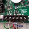
22k across outside terminals (Alarm ??) and 10k from right screw to where red wire is.

-
What just happened to my last post ?
-
Thats wrong.
Its running single eol not dual. The black wire should be in the empty tamper terminal
Ahhh ............. Just as well I posted pic before fitting everything then
Thanks James.How come it all worked OK on the bench? And I better take a pic of the door contact to see if that's right
Oh well .... At least I'm closer than I was yesterday
-
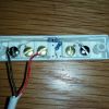
Just a quick picture of one the PIR's wired up (first attempt and it worked).
22k Resistor across alarm and 10k alarm to tamper / EOL (I'm sure one of you will correct my terminology)
I'll add more pics as I go through install which I'm doing in sections over the next few weeks.
-
-
al no one should berate anyone trying to learn
genuine question
How would you respond to someone having a go at servicing / working on your stuff that hadnt done it before?
No it's a good question with many considerations to take into account.
We often take on apprentices and people from other areas of engineering (fork lift engineers, plant engineers, cranes engineers etc etc) and some can absorb the technical side while other cannot.
We get a lot of wanna be engineers trying and often failing in our industry. I am all for letting people try and for them to learn but some people just don't have the right skill set (a bit like me with EOL for example)
It's no good taking on people who do not like heights, You have to test these machines and it cannot be done solely from ground control panels. The main consideration on the access machines is you have to remember people will be working at height for hours at a time and our job is to not only make sure the machine is reliable but ultimately SAFE and fit for purpose. This would be the show stopper for say an alarm engineer working on our machines. It's one thing if I mess un an alarm install but a different game altogether if you was to mess up one of our machines because you could potentially kill somebody (operator, other people in the work area etc etc)
-
Challenging at times to be honest but yes it is interesting. No day is the same and you always learn something new. The technology is moving forward in leaps and bounds as well which is sometimes hard to keep up with. We now have systems where you can "Swipe" in/off with your IPAF card or CSCS card to use the machine. We can log in from the office and tell who has used any given machine, what time they started, when they finished and also if say a company goes pop and they have machines on hire, lease etc we can remotely disable the machines from the office. The system also give you in depth report on service status, high running temps, oil condition etc etc. We work on machines up to 70 meters high.
-
lol id be fecked on your boom
What going up 125 foot or fixing it LOL
-
but could still wire your excel in....
LOL .... OK enough now
Yes but would show a mains fault.
You can stick a plug top on a flex for the bench test.
OK. The panel is double insulated I presume and I also presume the earth connected to euro block is there just for testing
-
Just install it , start with one sensor use two resistors and there's only a few combinations to do it, either way panel will report a fault
Global tamper should be last resort
Good advice. Could I do what sixwheelbeast suggested and set it up on worktop, then wire in just the keypad and one door contact, test that then remove it and try a pir ??? Can I do this with just battery power ...obviously the battery would need full charge.
Sounds good, I am sure someone will pipe up if your doing something wrong.
Maybe best to test bench the kit, during your first fix.
Maybe, if you can upload a better res picture.
The best I can make out it's a wiring diagram for a Vauxhall Nova.
It's for a JLG 1250 Ultraboom (cherry picker).
One of these.
Which by the way is controlled by logic controllers and envelope systems to stop it tipping over
-
I will bookmark thread and over next couple of weeks post back to let you know how I got on and maybe a few install picks. I am sure somebody else might find this handy (unless your an install engineer that fitting alarms comes easy to)
Just for an example here is a schematics of one machine I work on. This is a part page and there is another 17 sheets go with it. I have a Pcon 64 fault. Can anyone tell me where the fault lays (possible 3 answers)
-
hes an engineer like every kin diyer that comes on and 99% of them dont listen as they know better..whats the point man alarms are easy so why ask
It's not that I am not listening and never said I know better so please keep opinions to yourself if you cannot be civilised. If you don't want to help DiYers then why have a forum for them or choose to participate in it's content.
-
and it certainly is by the sounds of it,im surprised an engineer (sic) cant fathom basic circuits
It's a mile away from what I do. I work on electrical/hydraulic systems for lifting equipment and plant. It's low voltage but everything nowadays is controlled by ECU's, PCB's and motor controllers. Most of it is plug and play and set up with laptops and/or analysers. I don't really get involved in resistors, diodes and similar 'electronics' if that makes sense. It's basically car electronics on an advanced level.
-
Don't do this.
It is best to have a front door contact and arm on "final door set".
OK. Point well taken
-
As I already said I really appreciate your help, advice and honesty. I went for a wired system for reliability, cost and lesser maintenance over a wireless system (batteries for example).
I paid £145 for the system (new) with 100mtrs cable, 3 x pir's, 2 contacts, battery and the Pironix twin alert internal siren. Now I fully understand your comments about quality but most people like me would be in Homebase or B&Q paying over £200 for a Yale or similar wireless system. I just feel I wanted something better. I read loads of reviews on the Excel, weighed those up against cost which led me to my choice. If I wanted to spend a lot more I would have been speaking to you guys over the phone to get supply and install quotes and TBH me installing this alarm is better than no alarm.
I am not worried about it being monitored and not really that fussed about the dialler. I have good neighbours and my train of thought with the internal siren is make as much noise as possible in the hope it will either scare off any would be intruders (most of which in my area are opportunists) and also alert my neighbours who most of which have my mobile. The police where I live rarely attend burglar alarms so I could probably respond a lot quicker.
I still might go for the resistors and yes I did notice the manual saying about putting them on the PCB. If not I'll wire it globally.
I could miss out one of the door contact (planned for front door/zone one entry/exit) If I could position a pir above door knowing it wouldn't be triggered by post, junk mail and newspapers coming through letter box.
just get adt in job done
Doubt it with the issues neighbour has had with them. I want to install myself. I like the challenge
-
So going by your replies am I just better off using global tamper (after all that)
Don't get me wrong, I really appreciate your help and advice. It's a self fit home alarm after all and as long as it makes a lot of noise then that's good by me. Is anyone in the area I live going to be clever enough to break in and disable the alarm (and get past the dog) ? I very much doubt it but it's a new install and I may as well install it as best as I can so it's effective. I intend to (at a later date) purchase and install a text/speech dialler, panic button outside the bedrooms (mainly if kids are at home alone) and possibly look at linking smoke/heat detectors (to save me keep changing the batteries in my £10 B&Q jobbies I currently have).
-
Mark, the above is correct you 'can' loop it out with a resistor or program the input as not used. sixwheelbeast knows the better texecom stuff backwards. I would trust his info
Hi James
Not doubting anyone. Just trying to absorb info. I'm not an alarm engineer by a long shot and have never heard of EOL. I like to learn things and have a go myself hence I do lots of questions, reading etc before I play with things and do more damage than good. I will never make a living out of this (can you tell)
I did the same when I first put stair carpet down in my house. Done all the rooms but didn't have a clue where to start going down the steps LOL
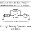
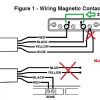
I have just found this image on another forum and it's specific to the Excel unit I have. It shows 2 x contacts where as I am only doing one at a time. Looking at this it makes sense I think with an EOL resistor and a shunt resistor. I presume I need to follow the right hand side contact in this image including the fitting of the 10k inline. If this is right can I connect the 10k under the left screw or does it go externally to the contact block ?
Edited to include image
-
Shouldn't need to link out unused zones, program them out.
EOL resistor inline with the loop and shunt resistor across the reed.
If you read through manual, page 13 quotes the following. Other info below that if that helps.
If EOL operation is selected and a zone is not
required then the zone link should be replaced with
a 10K resistor (supplied).
EOL Loop Threshold
Low (closed) Resistance - 10kΩ, 1%
High (open) Resistance - 33kΩ, 1% (or 10kΩ+22kΩ
The panel can distinguish up to four possible states; low
resistance (10kΩ) is interpreted as zone clear, high
resistance (33kΩ) is interpreted as zone in fault. Short
circuit may optionally be interpreted as tampering or zone
clear. Open circuit may optionally be interpreted as
tampering or zone in fault.
-
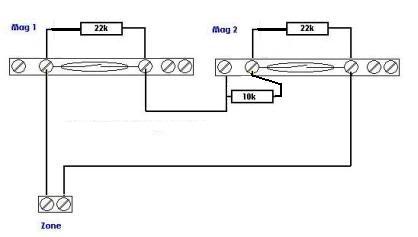
One diagram is taken from manual the other is one of my one artistic pieces
No zone types, just the S/C and O/C shown in one of the earlier posts.
Look, No matter what panel I would have purchased somebody somewhere would have said I should have got something else.
I can get the resistors I have into the contacts and Pir's I have. I just really need to knows how to connect them
-
So using this methodI should be doing something like this ? Just need to sort out the location of that other resistor
-
OK ..... Reading lots and trying hard so lets see if I am getting a grip on this.
If I use EOL and I don't want to use a zone I link it out with a 10k resistor. YES/NO ??
According to Figure 3d in manual, I need to place a 22k resistor on each device. Am I going to only wire each pir with 4 wires (power +/- white/green and 2 x alarm cables red/black) and resistor goes across red and black and not use yellow and blue. Door contacts the same but no aux power feed needed, leave them also as spares.
If so, where does the 10k in figure 3d go?
Please tell me I'm getting close
-
OK .... I'm reading manuals and websites as I come back at you all so bear with me.
My pir's are Texecom Premier Compact IR's (part number ACD-0001) and my door contacts are CQR (SC517 ... basic ones with no micro switch according to manual which is near on impossible to read even with my glasses on )
The Veritas manual says to wire door contacts (I have 5 screws in my contacts) Red and Black zone wires to the 2nd and 4th connections on contactor and then both yellow and blue to 5th connector. I am presuming the yellow and blue are normally tamper circuit which when using global tamper are wired along with other devices in series (via a choc block) into tamp circuit on PCB.
The Veritas manual then tells me to wire PIR's with 6 wires. Red and black to alarm, white and green to 12v / 0v, and again blue and yellow to tamp.
So, with EOL what's the difference as I presume the wiring above is for using global tamp. Do I just NOT use the yellow and blues anywhere and leave them tucked away as spare wires? And where do the resistors go. In the contactors and in the pir units themselves?
The system has been supplied with 10k, 22k and 33k resistors. What goes where? Also in the settings I have misc options (S/C = Tamper) and (O/C = Tamper) both with on/off options. According the manual it shows Normally Closed Operation = OFF/OFF, American Operation = ON/OFF, European Operation (one detector per zone) = OFF/ON and then High Security Operation (one detector per zone) = ON/ON.
To make things easier for me I am using one cable run per detector (ie; each detector will have it's own zone. 3 x PIR's and 2 x Door Contacts. Thus 5 x cable runs for the detectors. I then have the LCD keypad, internal speaker/siren (Pyronix Twin) and bellbox. I have purchased 6 core cable (in hind sight I should have got 8 but have 100mtrs of 6 core now so it will have to do.
Yep and also has odd Single EOL options too.
@Mark02 if your reading the manual you are best to use the "Figure 3d High Security Operation" diagrams and instructions BTW.HA HA That's one of the above things answered then
I've been typing for last 10 minutes -
I am an engineer by trade and work on low voltage/hydraulic systems so as DIYer's go I am quite good with wiring so after a spate of housing being broken into around my area I have decided to fit a burglar alarm. I used to have a pants wireless system but got bored changing batteries so ripped it out.
I have just received a Texecom Veritas Excel system complete with door contacts, bell box, PIR's and an internal dual sounder/speaker.
I have read the installation manual, understood most of it with ease BUT then came to the page about EOL, resistor etc
Now I have never come across this before so for this I am going to need help. I can fit everything where I want it, run all the cables, do the programming ..... just not the EOL without good advice.
The way I sort of understand it is that EOL increase security and when a device is tampered with the keypad/system will tell me what device has been tampered with. I also read it as the tamp option on the PCB is not used so bridged out. I am sure somebody will laugh at me and swiftly correct me if above is wrong.
So do I need EOL, is it more secure and more reliable, any pro's or con's to consider and I suppose the key thing where do the resistors go and how do I wire them. I have also read online about shunt resistors ..... are these related/needed.

 Thanks James.


Veritas Excel New Install - Eol Question
in !!..DIY Installers..!!
Posted
The internal speaker siren terminals are T - T - BA - SPX - 12v - 0v . The supplied instructions say tamper shold be connected in series with the system tamper loop. Also says 12v+, 12v- and BA should be wired in parallel with external bellbox (which I probably am not going to use .... local council don't like them).