

kwano888
-
Posts
26 -
Joined
-
Last visited
Content Type
Profiles
Forums
Events
Downloads
Gallery
Blogs
Posts posted by kwano888
-
-
6 hours ago, al-yeti said:
Ok so F means also an activation
Zone 3 is (First alarm activated)
Zone 2 is (also activated)
F doesn't mean fault in this case , it means first
Ok that makes sense. Thanks for the clarification. I'll monitor the Viper sensor as it maybe on its way out.
-
5 hours ago, al-yeti said:
Showing F on walk test?
No its in alarm mode. This is whats showing on the display after its disarmed.
-
The last couple of nights the alarm has activated and on the LCD RKP it shows the following :
1 2 3 4 5 6 7 8
0 1 F 0 0 0 0 0
What does this mean ?
I would have thought it would only show '1' on the zone triggered ? What is the 'F' ? I guess it's a fault code ?
All zones are in use. Zone 1 is front door, zone 2 is Hall PIR and zone 3 is rear patio shock sensor.
I going to change the backup battery as a start as I checked it yesterday and it's over 5 years old.
-
40 minutes ago, Simlec said:
Fantastic panels & probably the best looking keypad, I'm fitting another tomorrow morning.
if your budget can stretch go for the Euro App 46 and then add the wifi card to use your smartphone to control it (I take it your only fitting a bells only).
If your going to use there PIR detectors (wired) then switch off the blue led as they are to bright for domestic.
Thanks for the recommendation Simlec. Been browsing on Youtube and they look the business.
4 minutes ago, Simlec said:Sorry forgot you can't use wifi with App46 yet (officially
 ) you need lan or the gprs card.
Good shout, might be able to hook up to LAN as also wiring up his IP cameras so can bear that in mind. How much are the LAN cards ?
-
9 hours ago, Simlec said:
A Galaxy G2 is ten times easier to program than a Tex prem 24!
go with a Pyronix euro mini/46 or the Galaxy G2 12/20.
Accenta to a premier elite is a very big step.
Funnily enough I was in my local Enterprise Security branch today buying some 8 core cable and spoke to an installer there whilst waiting to be served. He suggested the Castle panel (now Pyronix) pointing to a wireless system on display and said they were pretty easy to fit for a DIY person. I got a price for a wired version and picked up a brochure... now for some research !
-
14 hours ago, al-yeti said:
None of them are straight forward , if your sticking to wired then galaxy may work for you , is it a commercial? Have you looked at texecom?
Euro mini?
It's a 4 bed extended detached house. Actually spoke to Sapphire Alarms today and he suggested a premier elite 24.
-
Or do I stick with the G4 and just double up on the zones to play it safe. Or is there any other panels which anyone can recommend which is straight forward to fit like the G4.
-
For a DIY person I have fit a few Accenta G4 for friends and family and few of my properties. But I need more than 8 zones in my next project and the Galaxy looks like it fits the bill. From looking online it looks more complicated ? Any thoughts people...
-
All resolved now. Moved the Green wire to the Black on the Sounder so they are connected together and the fault clears.
Thanks for everyones advice.
-
Yes if you link back does it all work fine on the panel and if wife up and link at bell ends does it clear the tamper?
Meant wire up not wife up lol
OK, will try that tomorrow.
Do you keep the wires in the panel whilst linking it or remove the green & black wires. Thanks.
-
Klaxon
Klaxon and Texecom merged...
If you loop the tamper on the panel does it clear?
then reconnect wires at panel and loop at sounder end without sounder connected does it clear?
Use the original link wire connect back on T & A ?
Not too clear on the photo, and I'm not familiar with the equipment, but it looks like you need to put a wire link between terminals 4 and 6 in the bell box.
Agreed, Terminal 6 must be Tamper Source
The Sounder instructions state :
6. TAMPER S - This terminal is only used when connecting two units in series.
(Note: remove series jumper when using tamper S input)
Instructions here :
http://www.klaxonsignals.com/images/Products/docs/datasheet/112.pdf
-
Hi all,
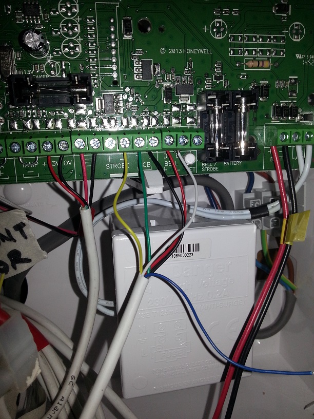
Need a little help and confirmation of the wiring connections to the Accenta G4 Panel and Sounder.
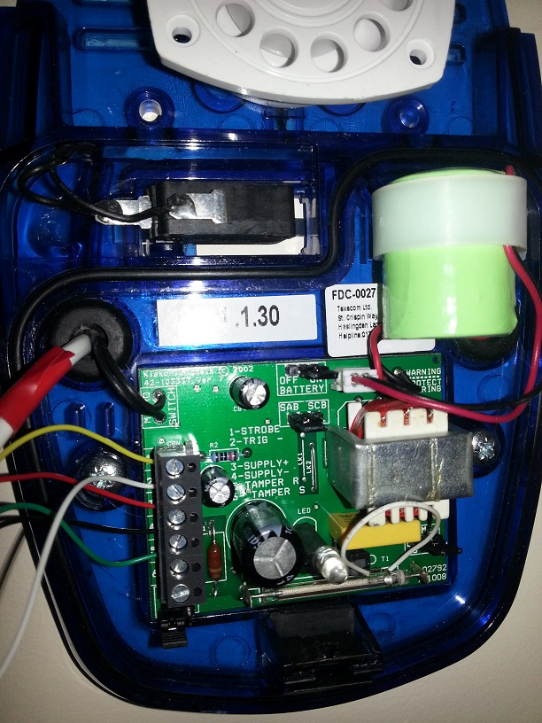
The sounder is a Texecom Flashguard Minn-XW which I have to install internally due to conditions of placing external sounders on the Flat building. I originally had an Odyssey 3E which was working fine.
The fault I am getting is 'Tamper Fault Lockout' on the LCD keypad.
I have wired the Accenta G4 panel for the Sounder as follows :
YELLOW connected to marked minus '-' on STROBE
GREEN connected to ‘T’
BLACK connected to ‘A’
(12v) RED connected to ‘D’ (positive)
WHITE connected to ‘B’ (negative)
On the Sounder instructions it states :
Panel : - Sounder
0v Strobe - connect to 1. STROBE
0V Sounder Trigger - connect to 2. TRIG -
+12v Hold off supply - connect to 3. SUPPLY +
0v Hold off supply - connect to 4. SUPPLY -
Tamper return - connect to 5. TAMPER R
So I have wired the Sounder as follows :
Panel : - Sounder
0v Strobe - connect to 1. STROBE - YELLOW
0V Sounder Trigger - connect to 2. TRIG - - WHITE
+12v Hold off supply - connect to 3. SUPPLY + - RED
0v Hold off supply - connect to 4. SUPPLY - - BLACK
Tamper return - connect to 5. TAMPER R - GREEN
I have checked the tamper switch on the G4 is 'clicked' in and the Sounder tamper switch also looks fine. Everything was working fine on the originally Odyssey 3E Sounder so I just need confirmation if I have gone wrong somewhere on the wiring side or not.
Pics attached.
Thanks all in advance.
-
Thanks bought LAP model from Screwfix £9.99
-
Thanks James and Al-yeti. Yes it was a bad neutral. Contact on the blue sheath not the copper !Just because you have a tester showing live on live , doesn't mean neutral is present
If it's an electrical problem have you checked the neutral is making contact? I assume its off a fused spur
Just one thing to check i suppose
I assume your taking precautions working on mains seeing as your connecting it or get an electrician to check it
Is it showing live on the neutral aswell? Then has to be as above
-
yes it is!
Thanks. Will investigate.
-
whats the day current?
Don't understand.
Just because you have a tester showing live on live , doesn't mean neutral is present
If it's an electrical problem have you checked the neutral is making contact? I assume its off a fused spur
Just one thing to check i suppose
I assume your taking precautions working on mains seeing as your connecting it or get an electrician to check it
Is it showing live on the neutral aswell? Then has to be as above
Yes off a fused spur. Flat has been totally rewired and the spur was installed by the electrician specifically for the alarm panel.
If it's showing 'live' on neutral then that's a the problem !
-
Newly installed Large size Accenta G4 with LCD RKP with 7Ah backup battery. Everything is working fine off the backup battery, PIR's, shock sensors, door contact etc. apart from the mains power. The mains red LED on the panel and RKP are not lit.
There is power going into the panel on the fused side and all the fuses look good. I thought the panel was faulty so took it back and got a replacement but the same identical thing is happening. I thought it maybe a faulty power supply unit in the panel. Is there a problem with the mains supply ? It is showing 'Live' on a live tester ! It's driving me crazy
and can't seem to work out the problem. Is there something I have missed ? Configuration or pins etc ? -
Could not agree more, but how to wire the device to your chosen panel are in the manuals for both products
I know but sometimes manuals are still not great and getting your head round it all can be confusing !
-
lol
Newbies gotta learn from somewhere... give us a break guys
-
NoRelay of smoke contacts connect to zone contacts
+&- goto +&- on the panel dc
Programme zones as fire zone 7&8 as said by jw
Unless that's what you meant anyway lol just seems as if your going to blow it up......
Yes that's what I meant lol !
BTW how do pro installers connect all there multiple red (+) and black (-) wires ? Is best practice to bunch them into a double block connector first then link it to the board ? Trying to keep it nice tidy as possible ☺
-
Thanks that seems straight forward enough.Ignore resistors for now and stick the alarm loop on relay contacts , tamper can be global running through each device but you can look at that after this is just to get your zone working
Resistors for eol better than standard wiring without
The chap from the electrical wholesalers seem to rate them and apparently a good seller. Had a look online too and appear to get good feedback.Your panel doesn't use EOL resistors.
Connect A&B to your zone. Program your zone for Fire. Check it works.
Is there a reason you have chosen an Exodus instead of other options?
I suppose as long it does its job what more can you ask from smoke detector !
Yes. Well not sure ! On the board there's 3 connections s : 13v, 0v, and fire.Is there a fire zone on an Accenta
Thanks all guys. So its a case of connecting to the A and B relay contacts together with + & - and that should do the trick.yeah 7 and 8 can be progged as fire
-
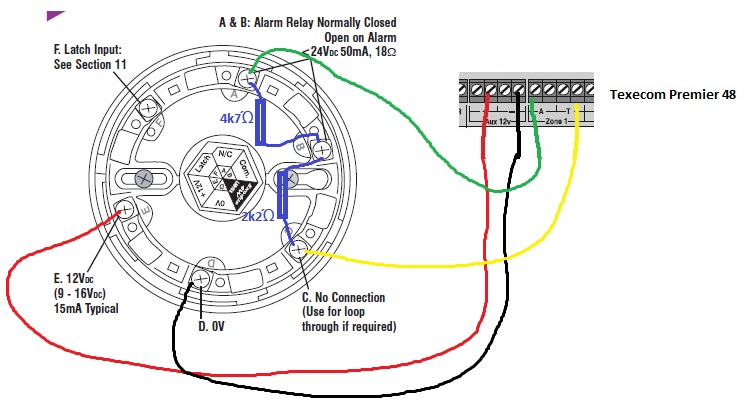
Need help wiring the Exodus smoke detector to my Accenta G4 panel.
Been doing some research but need someone to clarify the best way. Seen some people using resistors but no idea why !
I see from the G4 instructions that I can use zone 7 or 8 to connect other than the designated fire connections on the board.
Also seen this diagram picked up on here too :
Thanks in advance.
 ) you need lan or the gprs card.


Honeywell Accenta G4 error code ?
in !!..DIY Installers..!!
Posted
Zones 2 and 3 are on separate cable runs. No work has been undertaken. Hope no rodents been chomping !
Spot on. Keypad is in the front hallway where the PIR is located on zone 2.
Zone 3 - is on the back patio door (viper sensor).
I've updated the system on it now to 'Double knock' to minimise or help false alarms.