newuwave
-
Posts
18 -
Joined
-
Last visited
newuwave's Achievements
")


-
Sorry did not bother trying to reset 5E...just changed it for x type and all fine again. Will change 3E another day as I need 12 core to wire Test contact as using 8 cores already. 5E battery seemed fine too....so something else upset the 5E.
-
Good point about relay. I guess I can bring each test wire back to loft JB and just leave them on oc terminal rail. Log on in Engineer mode to view event log, test leads (reading voltage maybe?) on the relay output connected to terminal rail then test each at a time by linking it to 0V for minimum of 60 seconds with a wire..... I wonder if the relay event is logged ....could use this to see results. Thanks again.
-
One last thing. I mentioned earlier... I understand new boxes will stay in "hold off" mode until I connect +12v supply to the boxes, so I can make all connections in the new boxes, jumpers set to SCB and LC on then connect battery jumper and close boxes and finally connect +12V supply in control panel to the boxes. I read this is incorrect. Procedure should be... I understand new boxes will stay in "hold off" mode until I connect +12v supply to the boxes, so I can make all connections in the new boxes, connect Battery Jumper first so unit will enter Hold Off mode, then set to SCB and LC on and close boxes and finally connect +12V supply in control panel to the boxes.
-
Looking at my notes from 13 years ago I have my boxes wired as this..... But I am not using Aux/Fault to monitor tamper but am doing this.... and I did not use an output to carry out Test I guess because manual cites auto self test every 24 hours. The test input can be used to invoke a remote sounder test, this performs the same functions as the self test which is carried out once every 24 hours. To invoke the test the input must be placed at 0V for a minimum of 60s, during this time the Fault relay will open to signal the test is in progress. On completion of a successful test the Fault relay will close, if the test fails the relay will stay open. I recall 13 years ago it took me quite a few days to digest manuals, install and program the kit as it is quite complicated and hence taken me some time to refresh what I'd done. So today up the ladders I go to change the bell boxes to have some confidence in their reliability ....bit wobbly these days as an OAP approaching 70 so will take it easy. Thanks for the help.

-
ok - Thanks - will look into this.....I thought they were only for a stand alone communicator. I take it an unactivated output is floating or 12v and pulls to 0V when activated and the 100mA exceeds the requirement to activate the Test on the bell box?
-
Looked at how to use Test input to bell boxes....but I read 24-W panel only has one programmable output and I'm already using this to trigger an external GSM that rings people when the alarm is triggered. So I guess I cannot do this. Will try what you suggested to see if it clears bell 5E RHS flashing LED only. "Try triggering the strobe and see if they activate, then just the bell trigger and see if it clears hold-off."
-
ok - I will try what you suggest to see if the fault will clear. The 5E box right led only flashing has just started in this last week or so. Before that for 13 years its been like the Premier Elite Odyssey 3 with right and left leds alternate flashing. Alarm worked as expected and no fault or false alarms. I've not tried to arm alarm since 5e showed flashing right led only. But will look into it tomorrow as busy today. Thanks again.
-
A question if I may on removing bell box. I have planned to invoke "hold off" mode, then open the boxes, then come back to control panel and pull the +12V supply to the bell boxes, then back to bell boxes and pull battery jumper, then remove boxes. Or can I invoke "hold off" mode, check right LEDs are flashing to be sure of hold off mode, then at control panel pull the +12V supply to the bell boxes, then open boxes and pull battery jumper, then remove boxes. I understand new boxes will stay in "hold off" mode until I connect +12v supply to the boxes, so I can make all connections in the new boxes, jumpers set to SCB and LC on then connect battery jumper and close boxes and finally connect +12V supply in control panel to the boxes. Then I can test strobe and bell and alarm to see all is working ok. Sixwheeledbeast posted: "Using the test wire requires wiring as per Texecom recommendations otherwise you'll get faults on every test signal. The panel has to be programmed to expect the test is happening if you use Zones instead of fault input." I will look into the bell test wire method as you have kindly mentioned....I'll have to google this as I cannot recall reading any documentation on it. Thanks again for the advice.
-
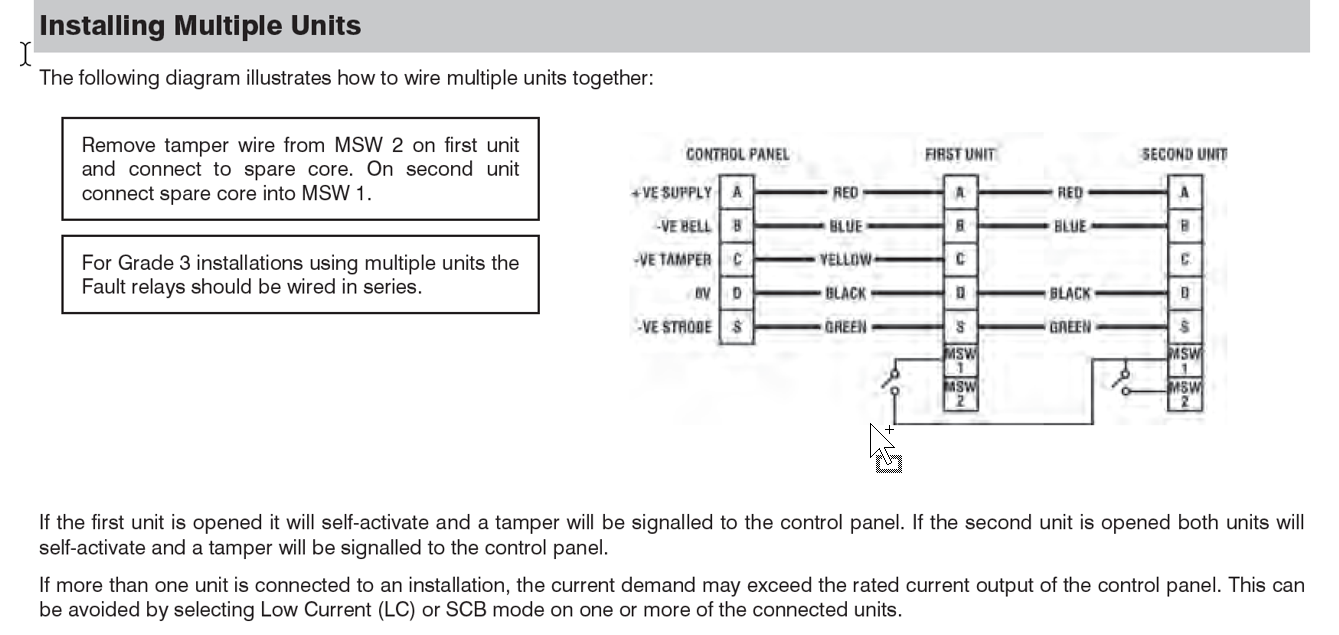
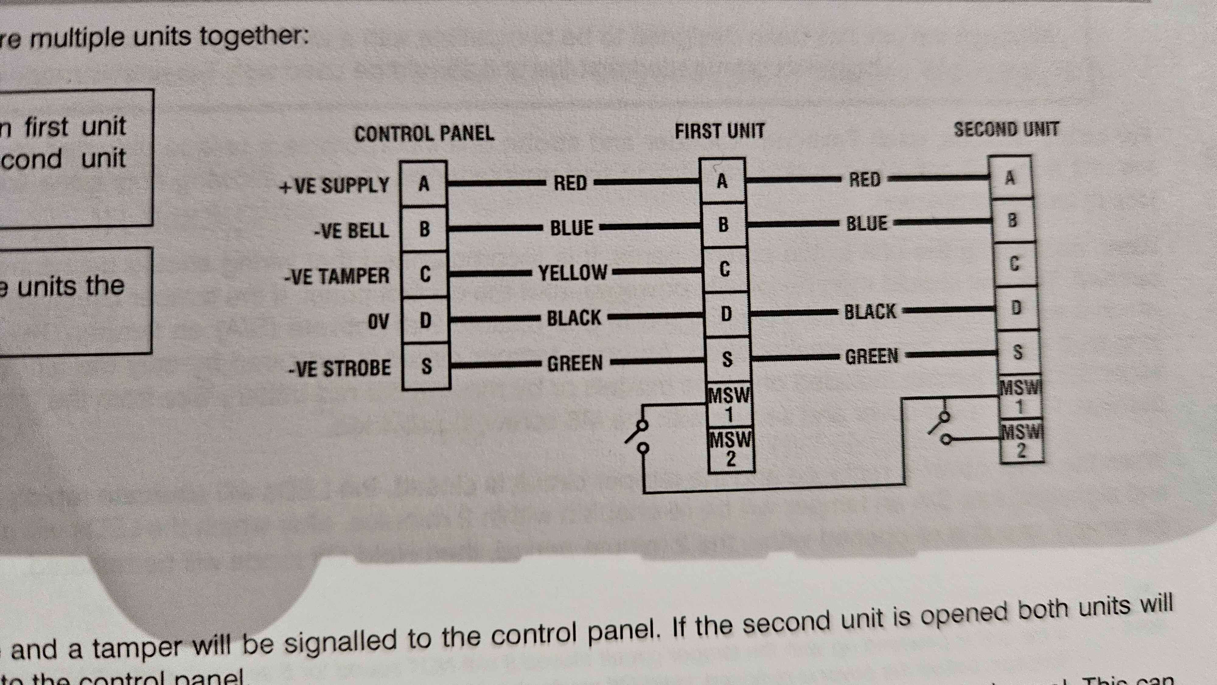
I do apologize for the mistake I made in my previous post. The keypad zone 1 is not connected to MSW1 and MSW2 but is connected to the bell box fault relay contacts which are connected in series. This posting error was made in haste whilst turning on the TV to watch Strictly and being called to come to the table for dinner.
-
Looked up my wiring diagrams and I have 8 core back from each bell box and wired like this in JB in loft. Been working fine for last 13 years...or have I missed something? Thanks for info on test wiring. Maybe should add......Z1 tamper of keypad 2 wires...one to MSW1 the other to MSW2
-
Thanks again. I did think of just replacing the batteries.....but after 13 years I am happy to just replace both bells which I have bought....plan to change them Monday. No I do not have test wire connected......If I have spares I will do so when I swap them over for future ref. I have a juction box in the loft that connects both box's to the control unit so can individually check the fault relay of each bell box if I wanted....also made it a bit easier doing wiring. Will be back for your help if I may if new box's don't sort it.
-
Thanks for the advice. One bell box reports a problem ....I assume battery.......suspect box 5E (I have one of each Odyssey 3E & 5E) is also just flashing slowly right hand LED...."Hold off mode" I believe and I cant clear it. The 3E is fine. At 13 years old I've just decided to replace both bell box's rather than the batteries to hopefully avoid further issues with them. Thanks for clarifying the current connection method is just fine for my needs. I'm no alarm expert and at the time did not pick up from the documentation I had about using Aux input for this.....I guess I must have missed this or the lack of explanation on how to use it in the documentation and then swayed by write up on zone types and keypad outputs which did the job. I sort of agree "overkill" but I enjoyed setting this up with all the "bells and whistles" (no pun intended) and thought it a good idea to know if bell had a fault. Great reliable kit, just sorry to see Texecom have distanced themselves from DIY but I understand why and great forums like this will hopefully keep me going if I ever need to replace the whole system with another Texecom Ricochet system.....hopefully not for many more years. Thanks again.
-
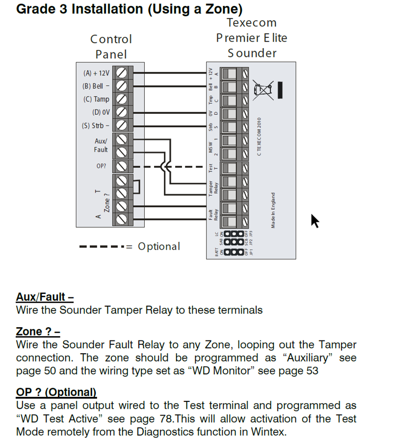
Hi – I have a Texecom Premiere Elite 24W and bell box’s grade 3 so I am monitoring them for faults. As I have used all wiring zones on the 24W I have wired the bell box fault back to the keypad and mapped Zone 1 on keypad to Zone 5 on the 24W. On the 24W I have set Zone 5 to be type Auxiliary as I understand this will only log a fault as a message and not activate the alarm. This is how it’s been for 13 years without issue. I am going to change the bell box to the new X type, again grade 3, but just want to check this will work as I expect or should I change type to PA Silent or other zone type? Thanks for any advice.
-
How to replace Texecom sounder batteries....Question?
newuwave replied to newuwave's topic in !!..DIY Installers..!!
ok - thanks sixwheeledbeast. I will be logging in via keypad in Engineer mode.....I have wintex too but to do things like change pir batteries I like to use keypad and log in as Engineer. So no need to do anything except invoke Hold-Off mode, open sounder and replace battery...great - thanks. Just another question if I may. No plans to change sounders but I read new sounders do not need battery change.....so do they have them? I thought sounders used their own battery for the siren.....I have had a power cut once many years ago when it was off so long the control battery died and then the sounders went off.....I think for 20 mins or so...can't recall exactly. I replaced the controller battery after that. Thanks again. -
Hi - I have a Texecom premiere elite 24W Ricochet kit which I installed back in 2013 and during a recent power cut the panel reported failed battery for the external sounder. I must admit its been on my list for a while but I've never got round to it due to other jobs. Anyhow there are 2 sounders connected, a Premiere Odyssey 5E and a Premiere Odyssey 3. Looking at the manual and I recall during install I was required to connect the wires to the units first then to the control panel second, the sounders being initially powered from the control panel and I seem to recall a jumper inside the sounder used to connect the sounder's own battery before closing the lid. So for my question, just to be sure I do not set off the sounders as I unstall new batteries. I read I can either invoke sounder Hold Off Mode by activating the strobe 3x within 30 seconds OR simply connect the strobe wire inside the control panel to the 0V....which I think I will do as I plan to change the controller battery too. The sounder will indicate Hold Off Mode by flashing the Right LED only, then I can open the sounder without setting it off. Now once opened do I need to remove the sounder battery power jumper so that when I install a new battery the sounder itself is not connected to its own battery? I have made a note as I am using 2 sounders that there is an order/sequence of installing and connecting the sounders to their own batteries and closing their lids so I expect to follow this. My question is regarding the pulling of the sounder jumpers which I am expecting that I should do so that the sounders are in a state as if just installed - lids off and not connected yet to their own batteries until I plan to close the lid. I'm no alarm expert but I hope my question is clear enough for someone to confirm/advise if I have the right idea or should do it some other way. Thanks for your help.