

Derek Foote
-
Posts
10 -
Joined
-
Last visited
Content Type
Profiles
Forums
Events
Downloads
Gallery
Blogs
Posts posted by Derek Foote
-
-
OK Guys.
I know you must be pulling your hair out by now trying to get me to understand what to do but please bear with me.
al-yeti, you say to disconnect all the triggers and connect one trigger to the bell trigger. Which one is the bell trigger.
-
I have now numbered the photos of the wiring, I hope this helps to understand what I have done.
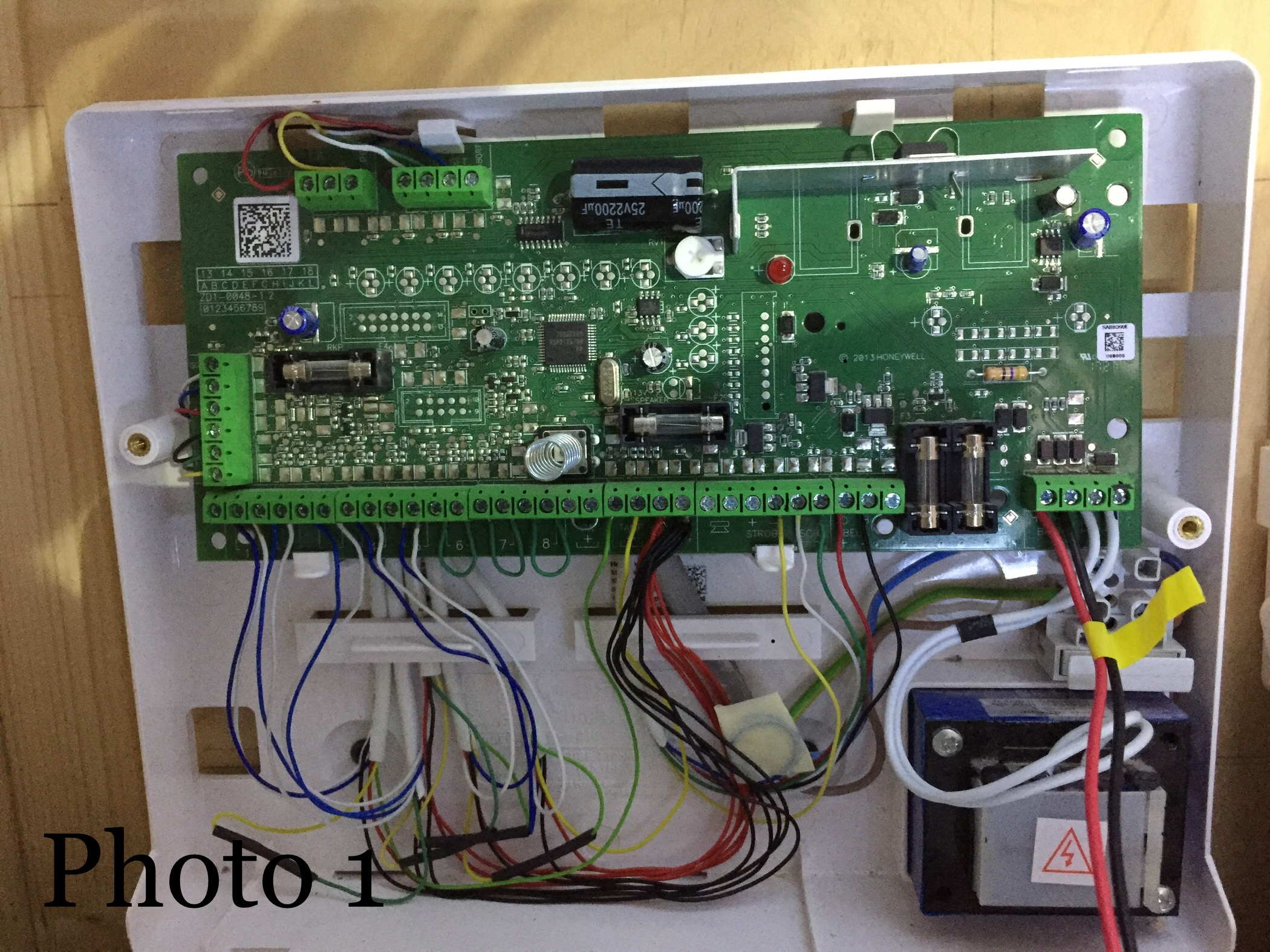
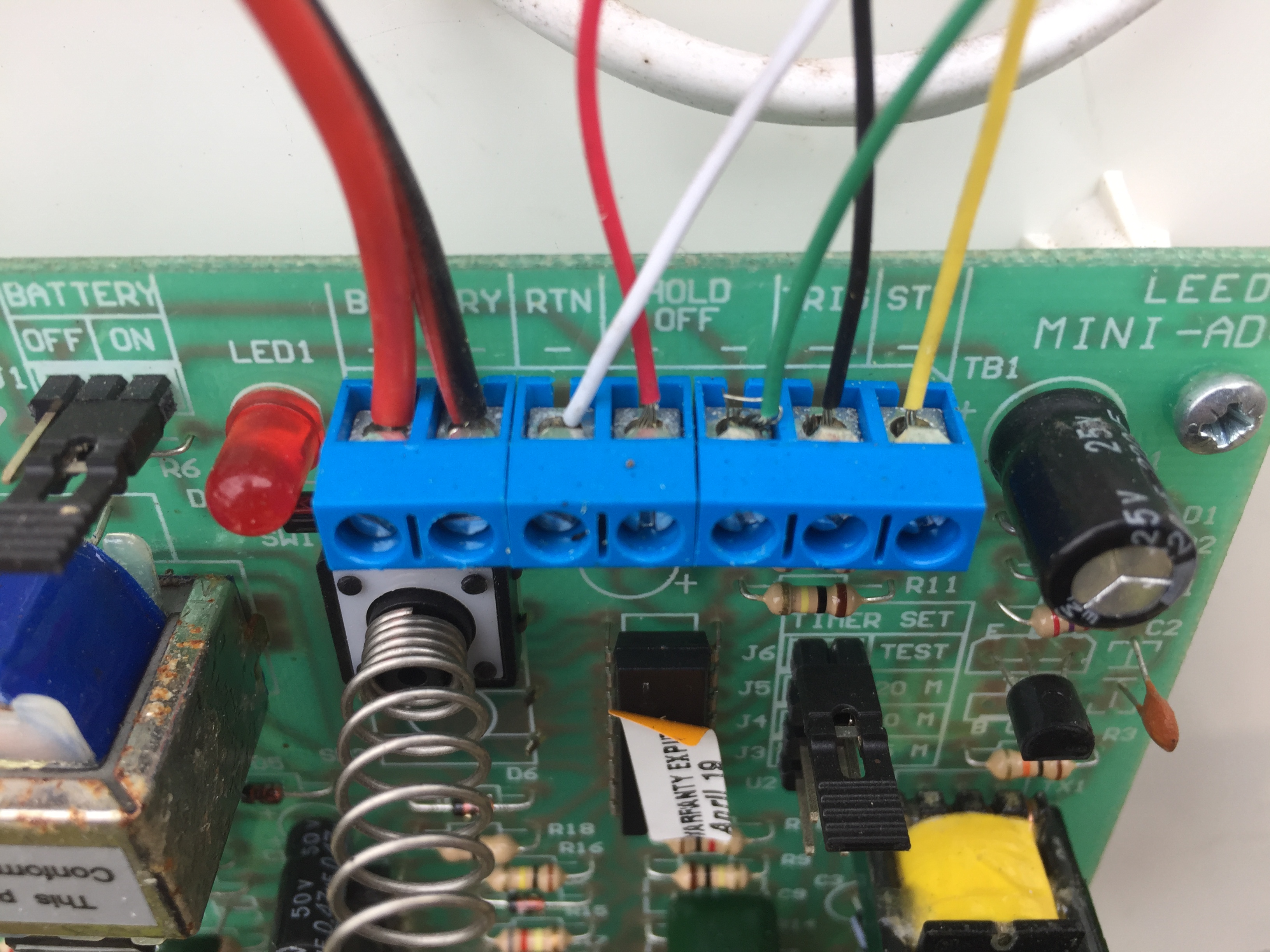
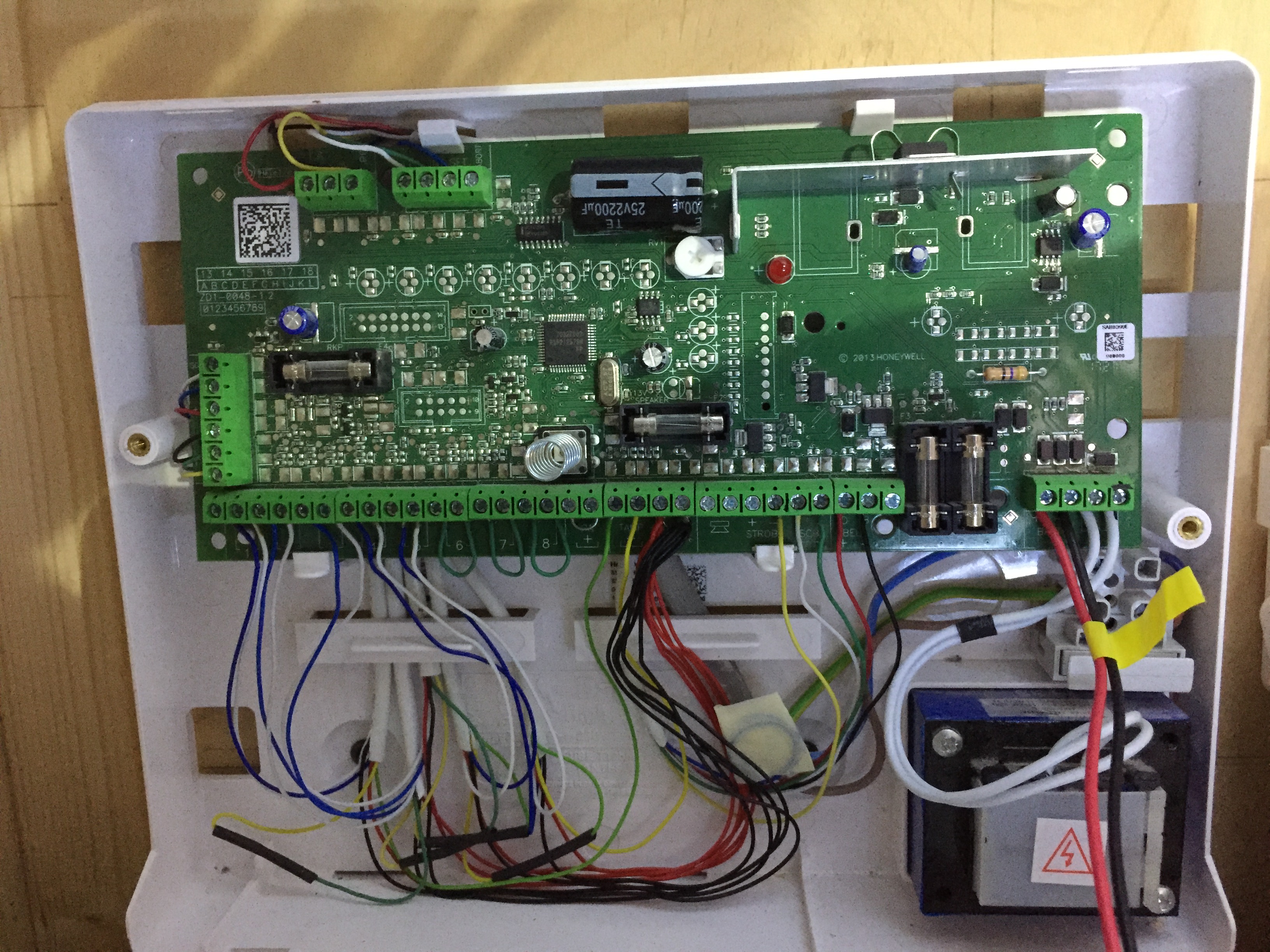
Photo 1, overall view of the Accenta G4 panel
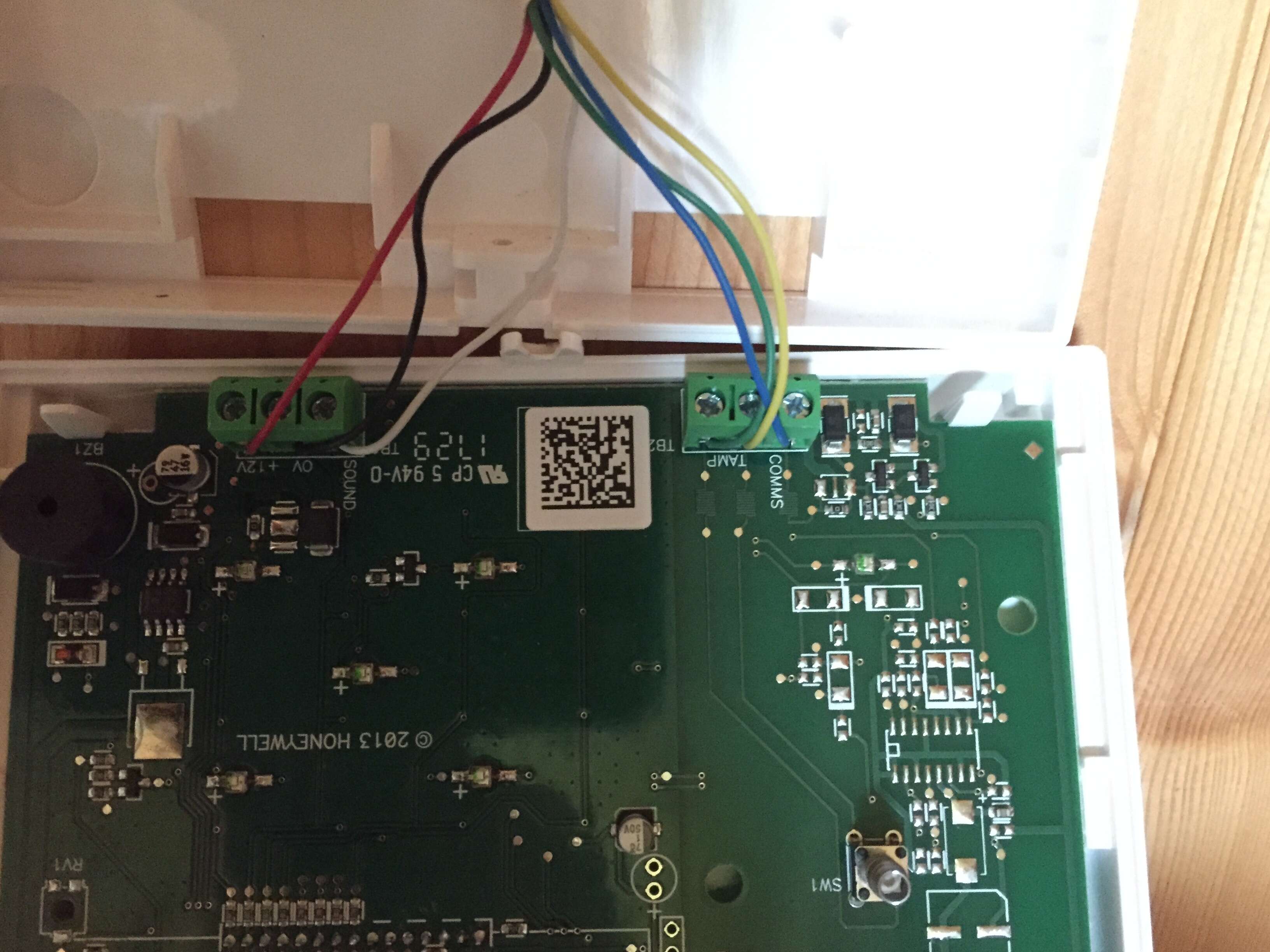
Photo 2, Outside box connection on panel
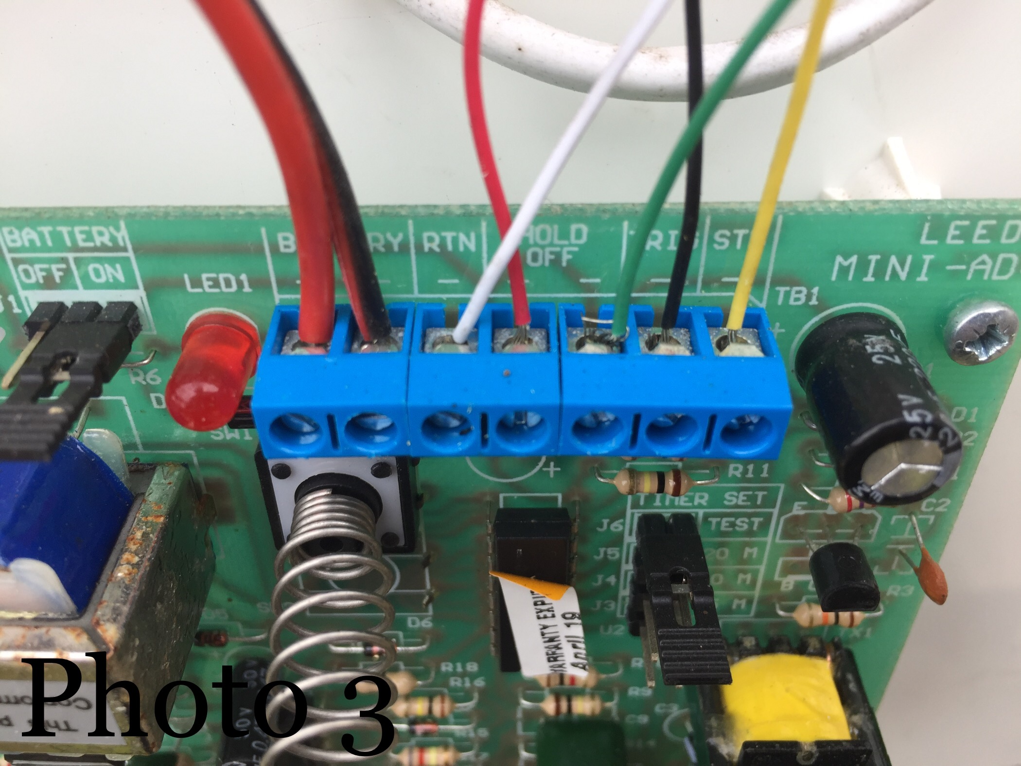
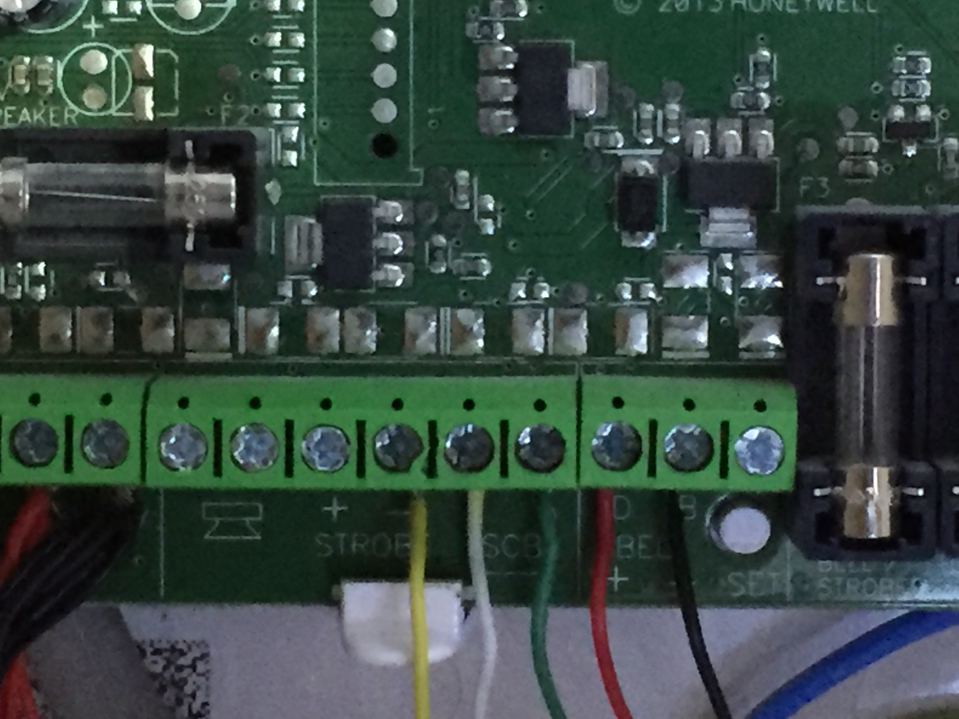
Photo 3, connection to outside box
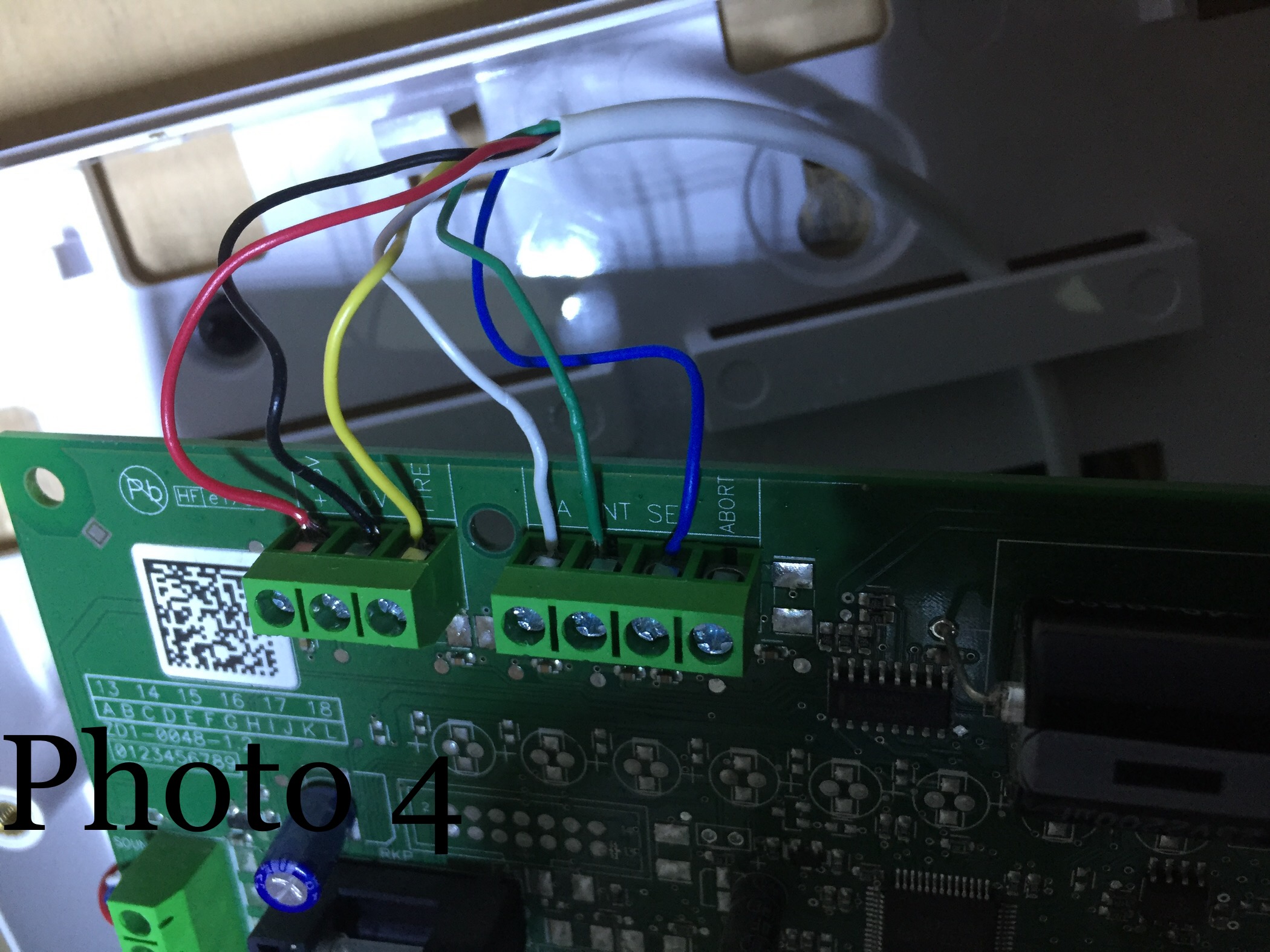
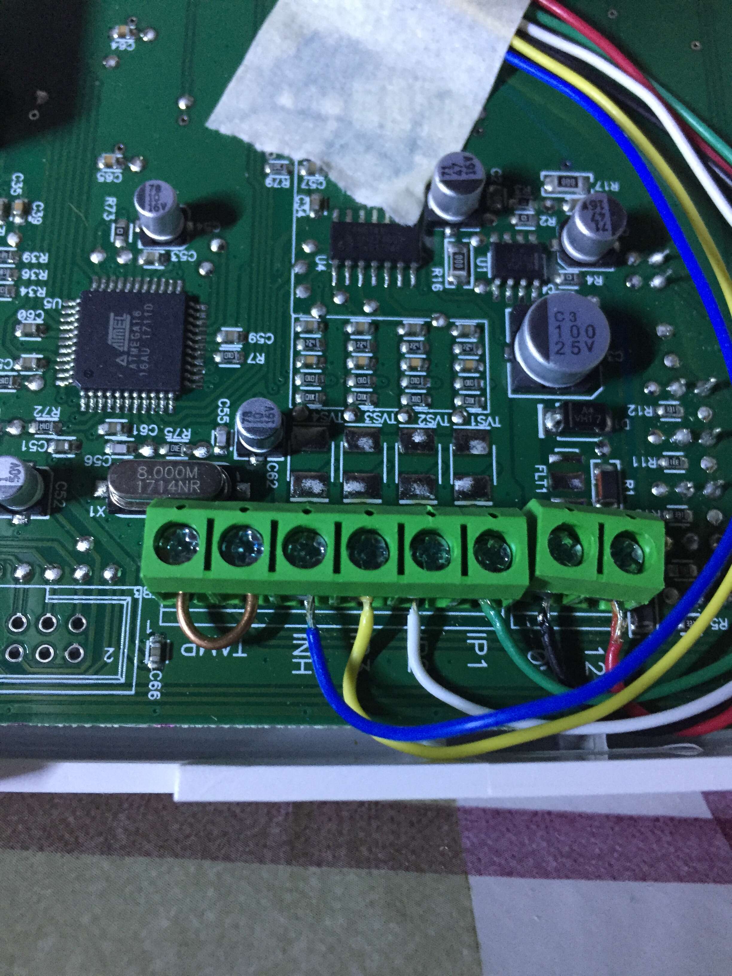
Photo 4, connection of speech dialler on panel
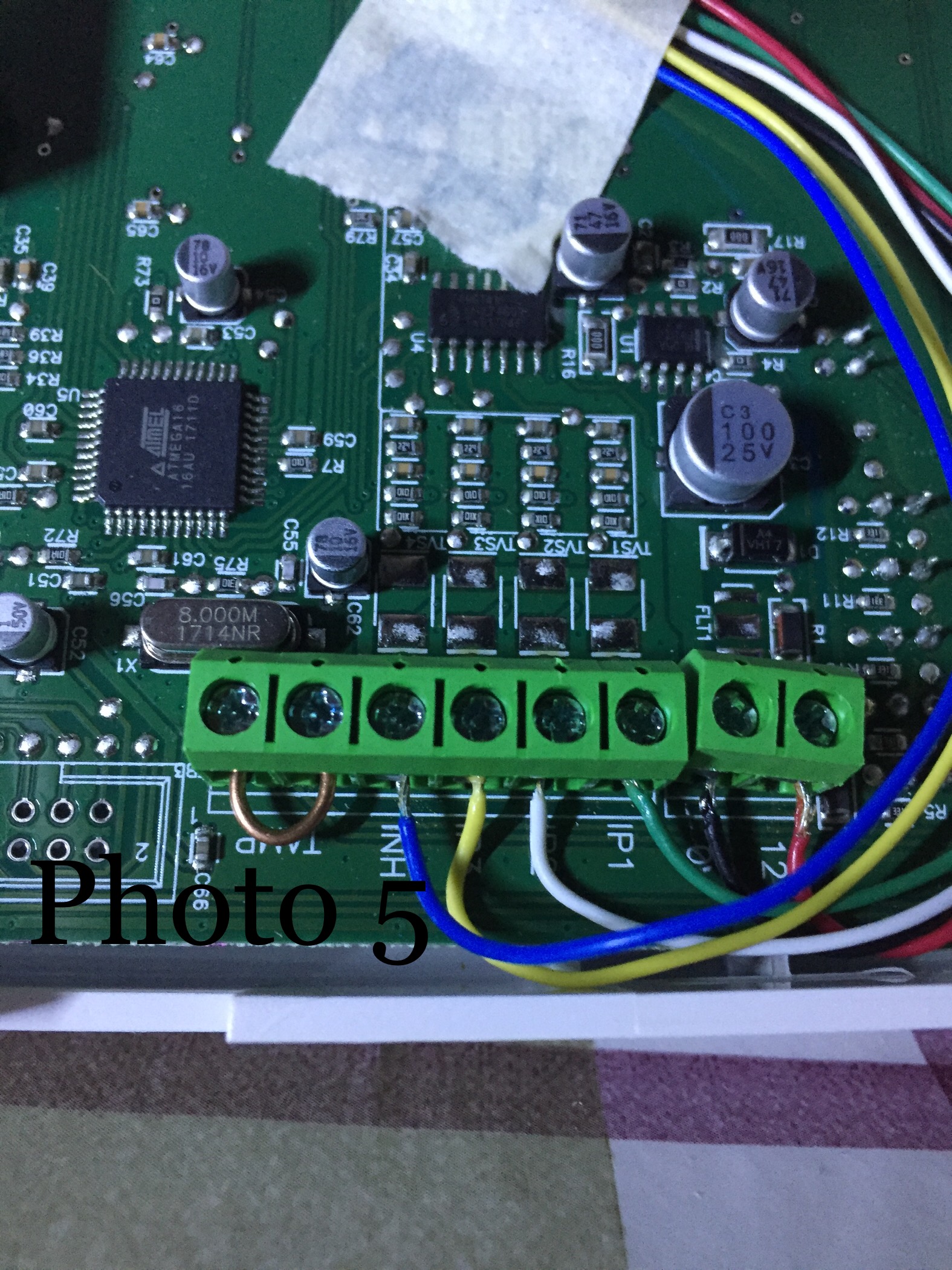
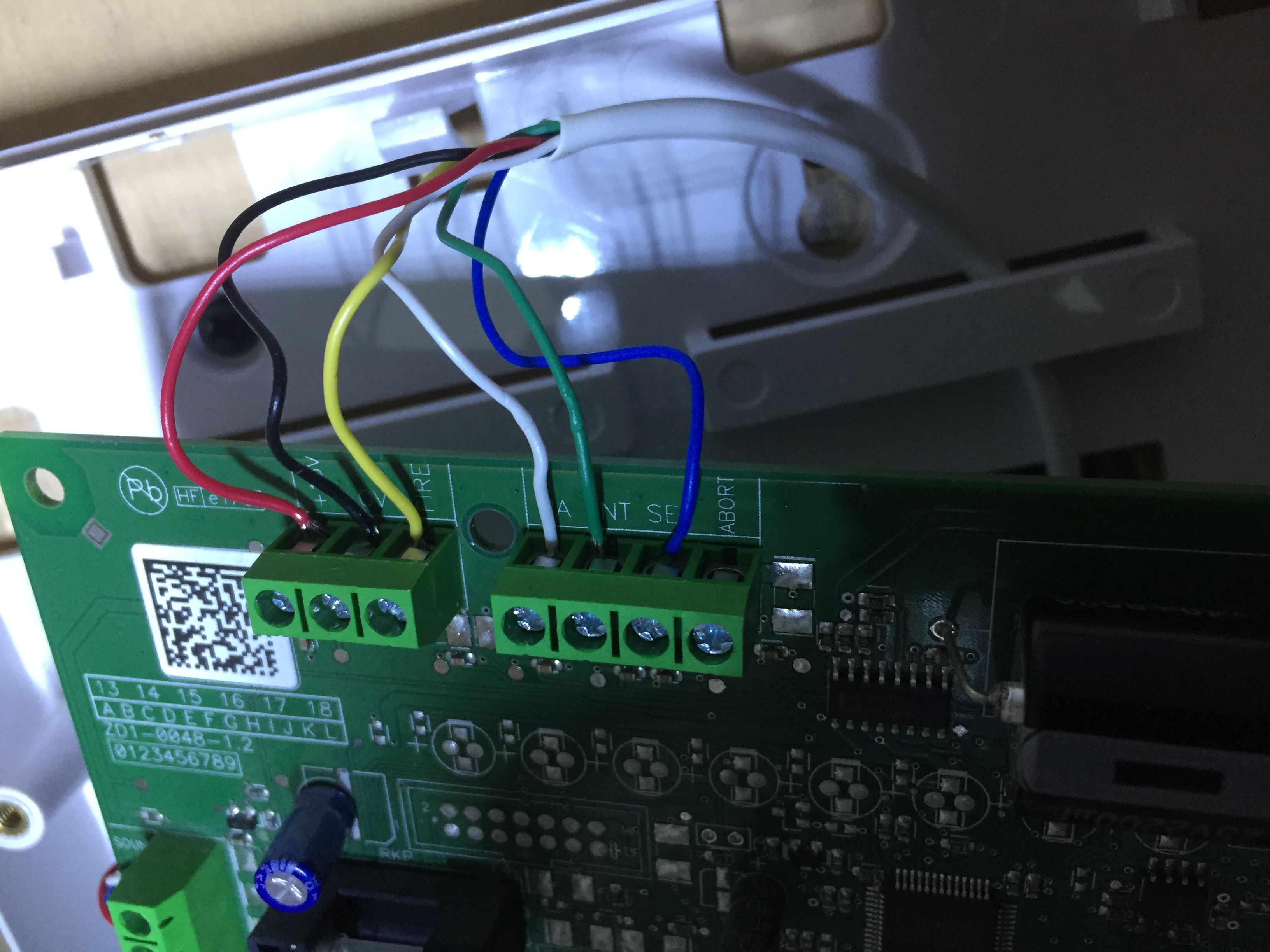
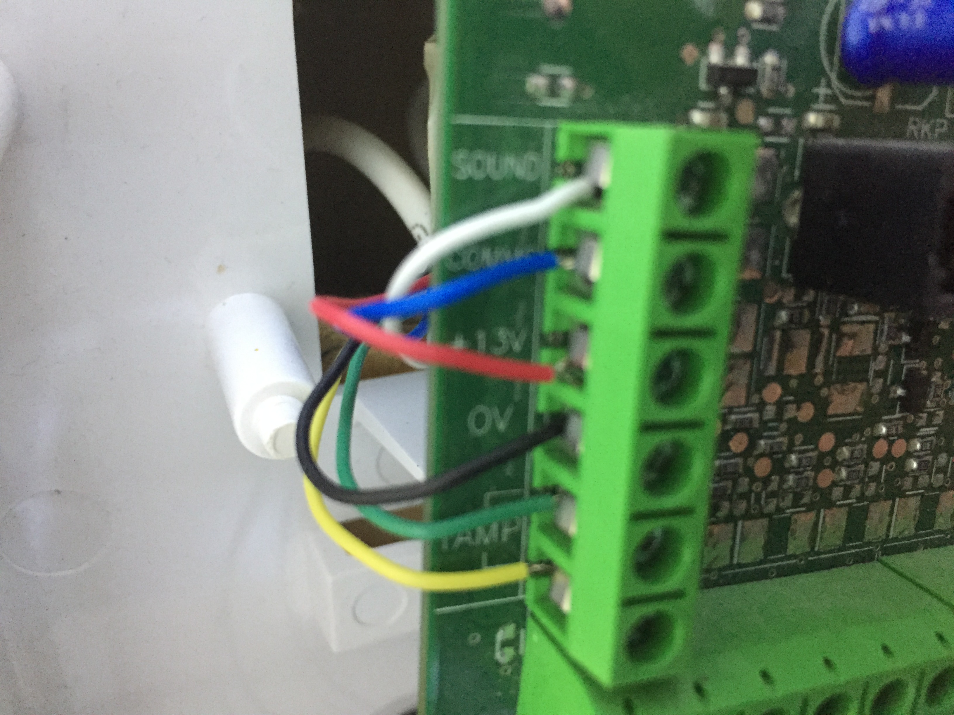
Photo 5, connection to speech dialler
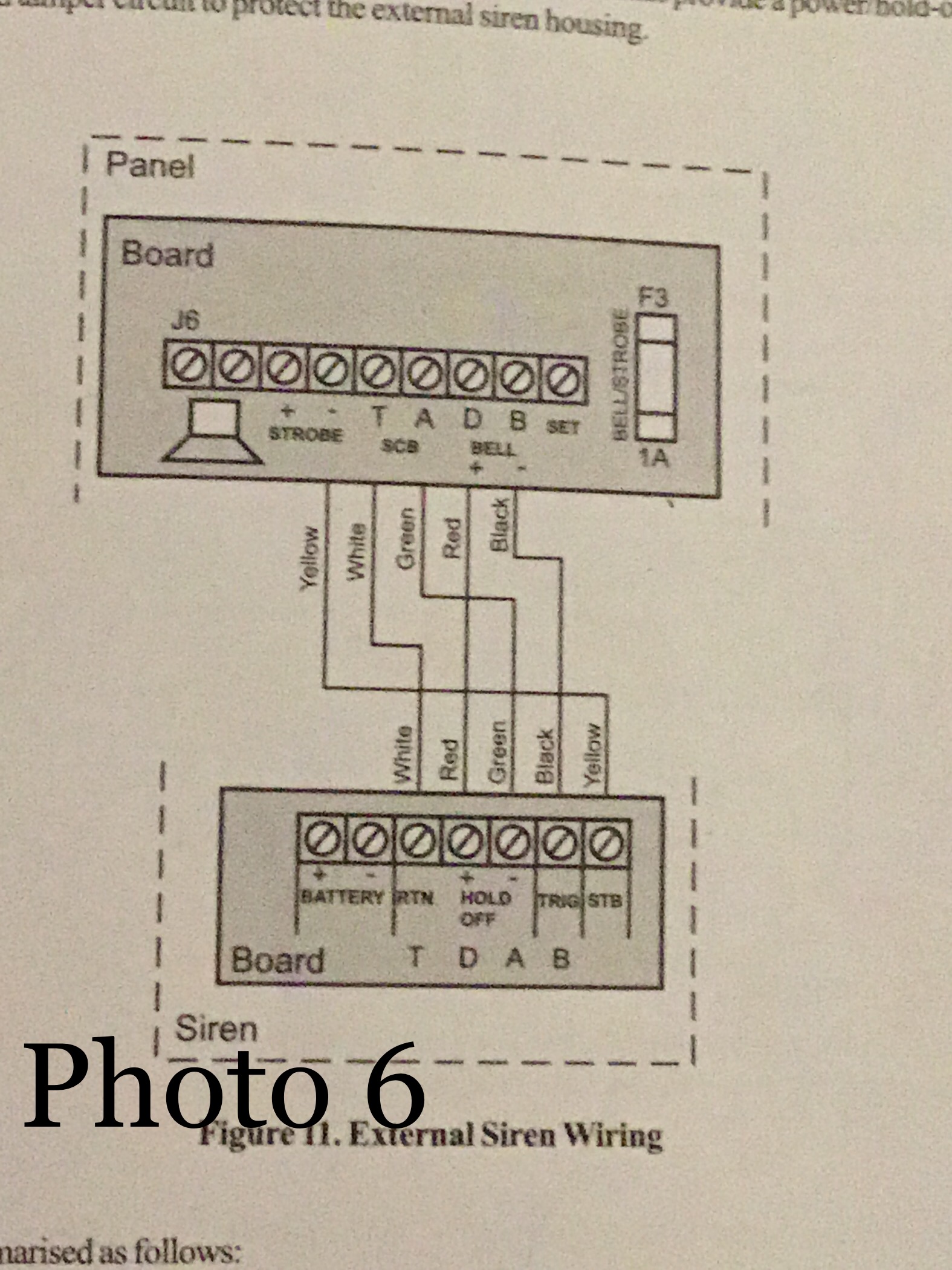
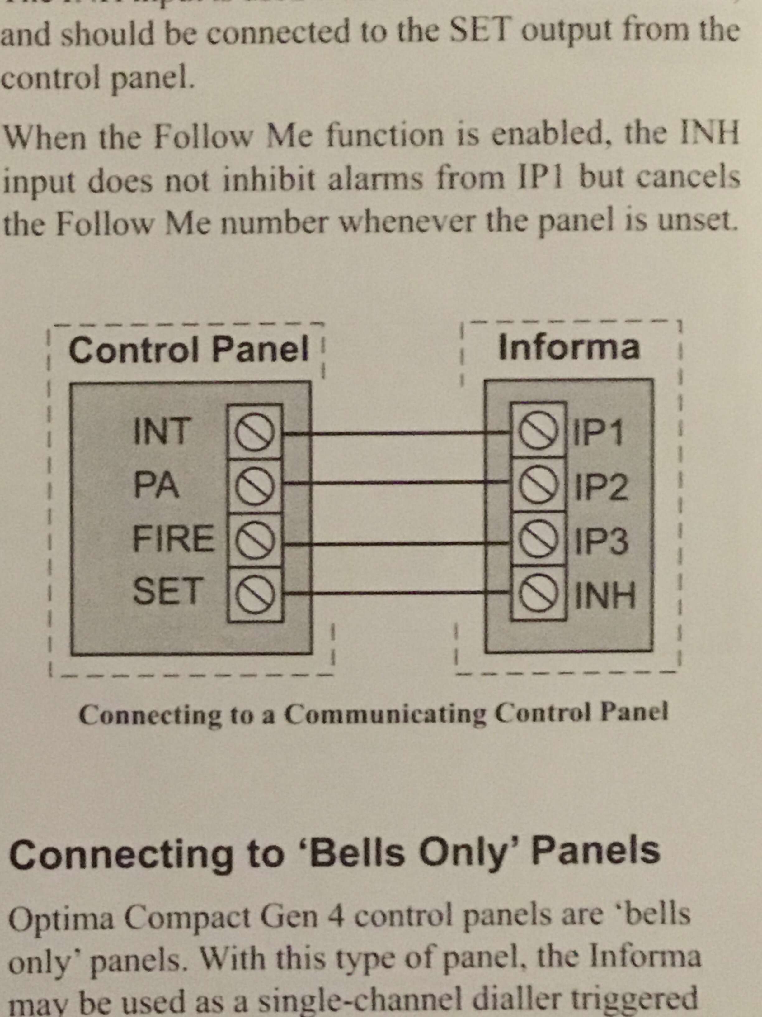
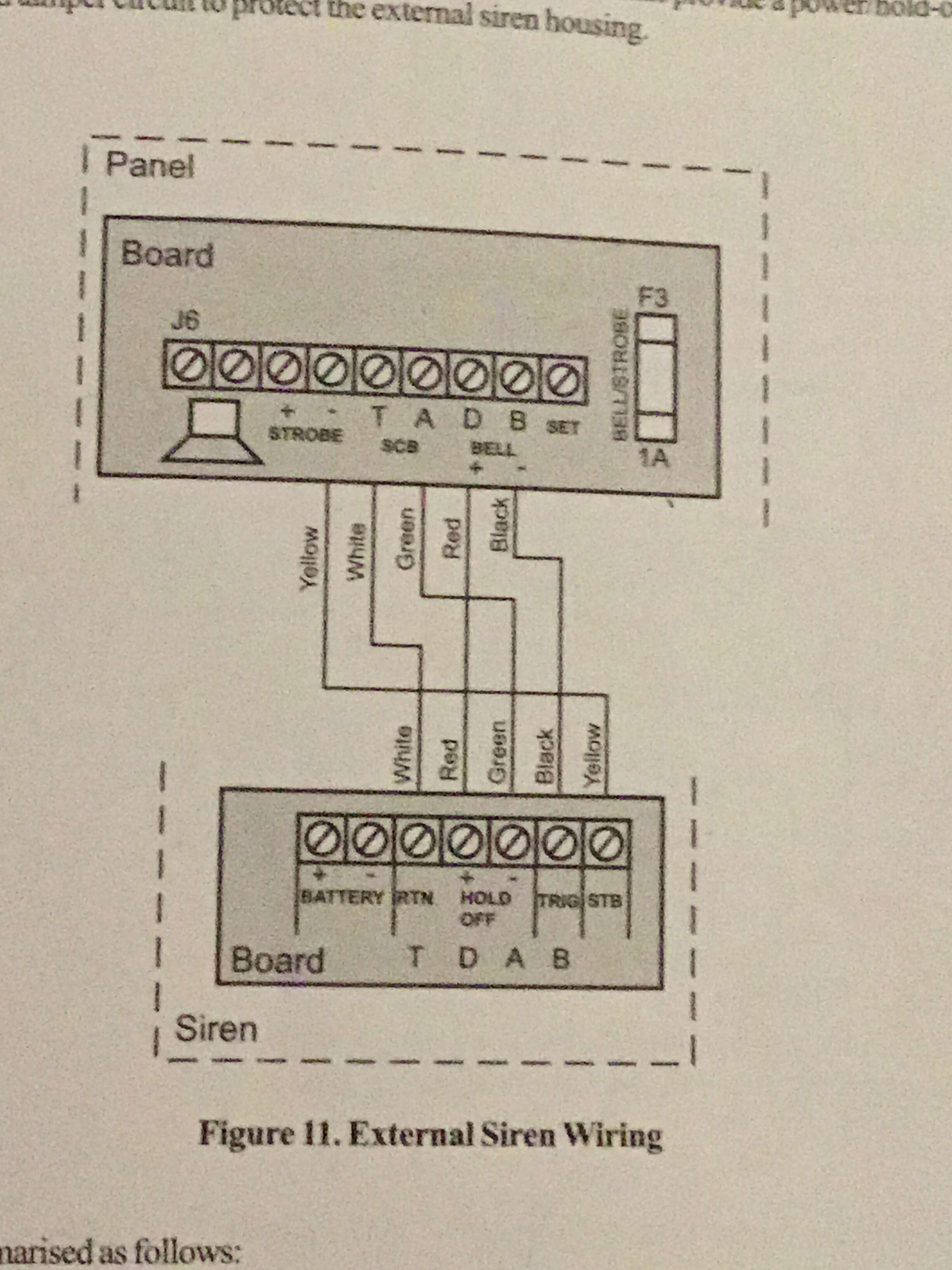
Photo 6 wiring diagram for outside box as shown in Accents manual
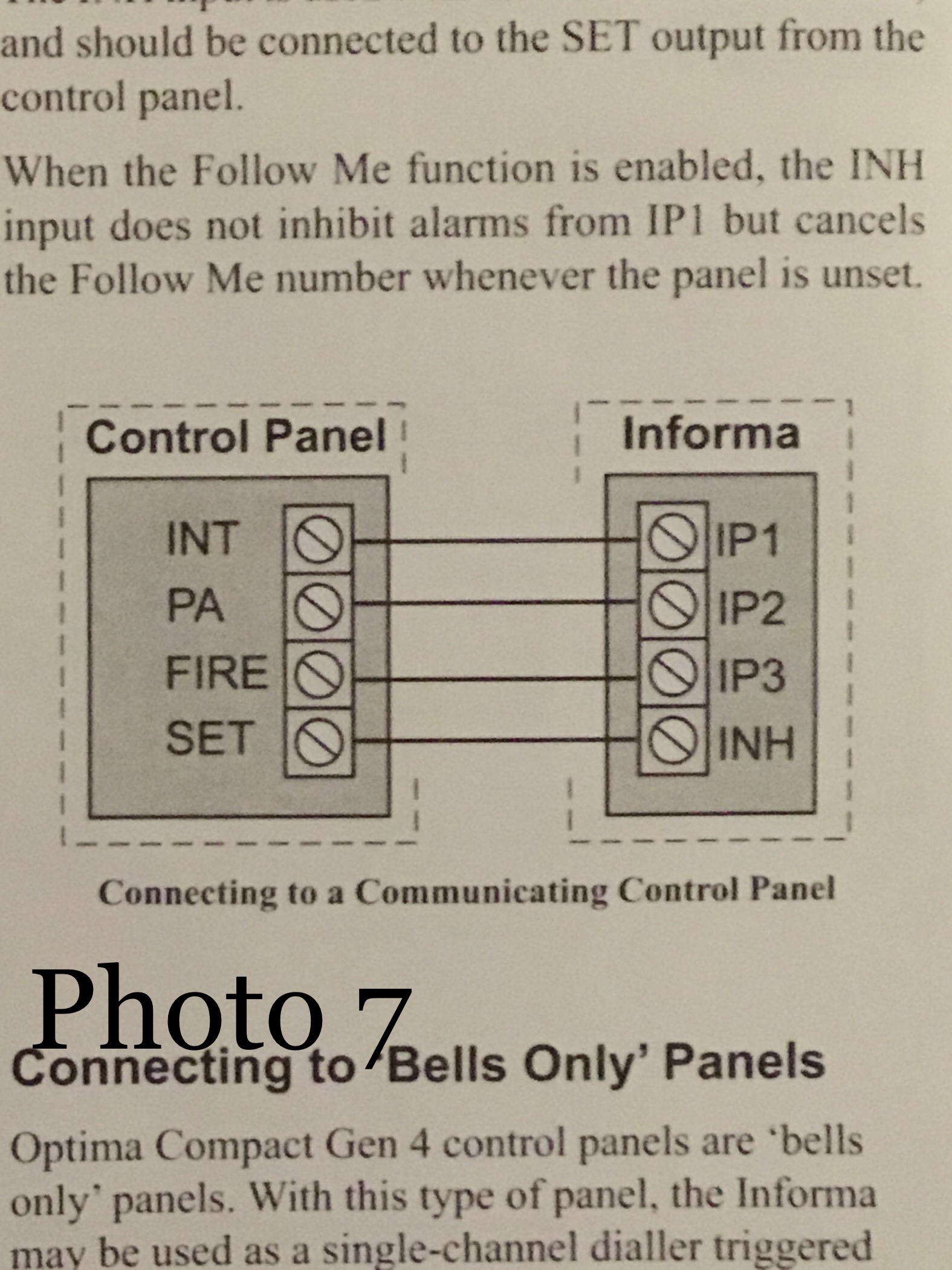
Photo 7 wiring diagram for speech dialler as shown in speech dialler manual
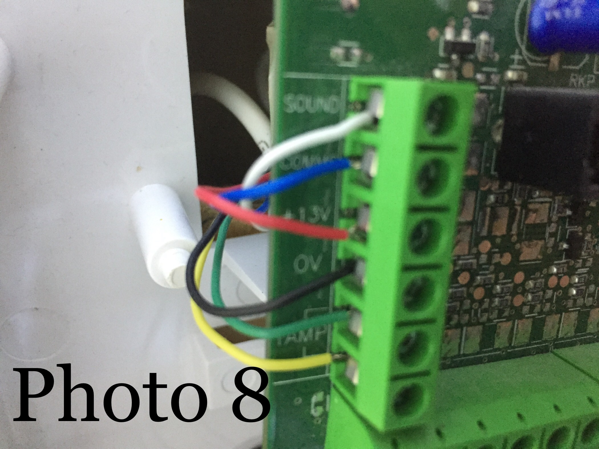
Photo 8 connection of keypad on panel
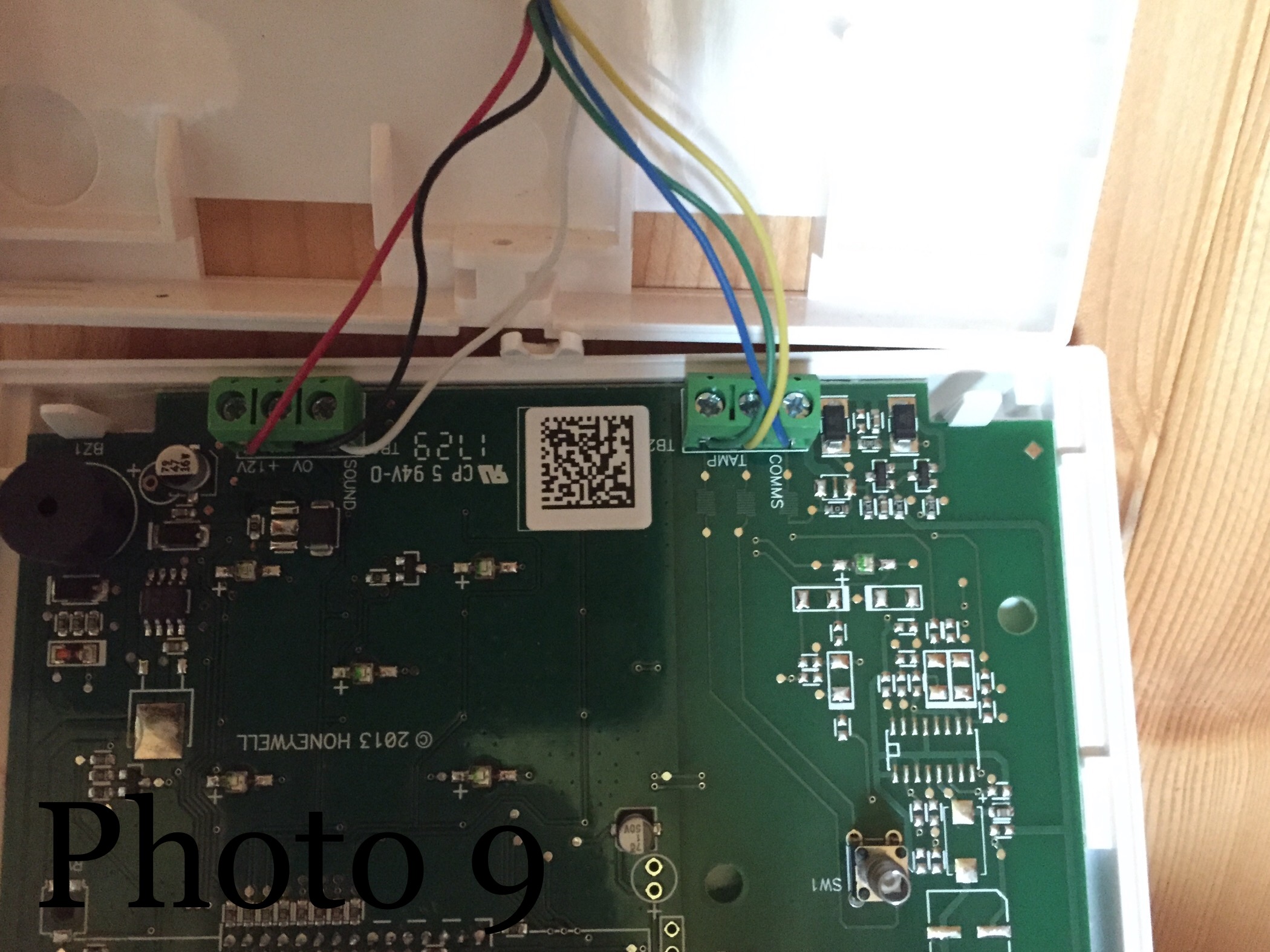
Photo 9 connection to key panel

-
I have just looked at what i have sent and it looks like they have not been sent in the sam order that i loaded them. will try and sort them out.
-
I have taken some photos of the wiring, I hope this helps to understand what I have done.
Photo 1, overall view of the Accenta G4 panel
Photo 2, Outside box connection on panel
Photo 3, connection to outside box
Photo 4, connection of speech dialler on panel
Photo 5, connection to speech dialler
Photo 6 wiring diagram for outside box as shown in Accents manual
Photo 7 wiring diagram for speech dialler as shown in speech dialler manual
Photo 8 connection of keypad on panel
Photo 9 connection to key panel
-
There is no mention of changing triggers in the Accenta engineer's manual.
-
I changed the four inputs triggers on the speech dialler from active low (LED on) to active high(LED of). All that happened was that the speech dialler instantly went in to the dialling sequence.
-
I am not sure about thees triggers. I had noticed the comments on the previous posts reference inverting the triggers but i can't find any reference to this in the manuals.
-
Hi, I have just finished installing the complete system and it was while testing the system that i discovered the problem. Every thing tests ok...except....the speech dialler won't dial out until the alarm has been reset after an activation and then it will go through the correct sequence.
-
Hi Pradeep So,
I know it was some time ago that this was posted but i have the same problem. when you say you connected the telephone cable the other way around are you referring to the PCB terminal on the speech dialler A and B and changed the Red and White wire the other way around as in terminal A Red instead of white and terminal B White instead of Red.
Regards Derek

Informa Speech Dialler Only Dials After Entering The Password
in Control Panels (Public)
Posted
I connected it to bell- and Its all working fine now, thanks to every one for your help.
Regards Derek